¶ The information on this page is somewhat outdated. Please refer to the Discord #guides for the latest info on wiring, and it'll be updated here once complete.
The PrintNC uses many electronic components that need to be carefully wired together. This page will explain what the main components are, what function they perform and how they interact with each other.
For information on the electronics enclosure, see the electronics enclosure page.
The wiring of the PrintNC involves manipulating high voltage current. Poor wiring can lead to increased chances of fire, power surges, arc faults and other serious consequences.
In addition, this can also lead to serious injuries if done improperly.
You are doing this at your own risk. When in doubt, have your work reviewed by a certified electrician before powering up.
¶ Bird's eye view of the electronics
This is a very generic diagram on how things will be connected.
The picture below shows the orientation of Front/Back/Left/Right which may be useful when following the wiring instructions: 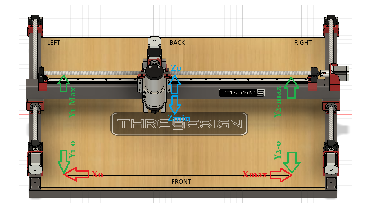
Both LinuxCNC and GRBLHAL can be used in either application. Most users follow the diagram below and use an external PC with either GRBLHAL or LinuxCNC.
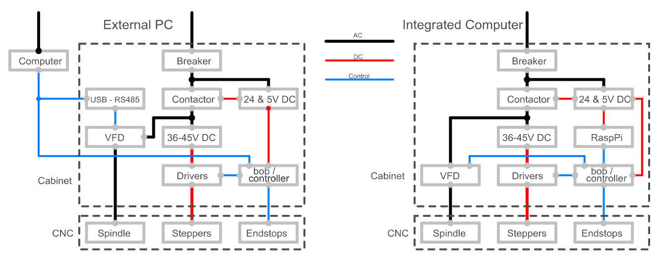
¶ Descriptions of the main electronics parts
¶ 24V/5V PSU
This is the main power supply for low voltage components (except the stepper drivers). Your actual PSU requirements depend on the other components you use. A 24V PSU could be used to power a Mesa Board, the Contactor or the inductive switches. If you use a Cisco PSU you may be able to use the 12V and not need an additional PSU.
¶ Contactor
A contactor is an electrical device which is used for switching an electrical circuit on or off. It can be switched on and off by applying an electrical current to a specific part of the contactor, known as the "coil". A contactor also has one or several inputs and outputs known as "poles". One input pole is connected to one output pole.
Like many switches in electronics, a contactor can be NC (Normally Closed = by default, the current pass through the poles) or NO (Normally Open = by default, the current cannot pass through the poles).
When the coil is powered, the contactor reacts depending to its type :
- If it's a NC contactor, the poles will open the circuit, disconnecting the poles
- If it's a NO contactor, the poles will close the circuit, connecting the poles.
A contactor can also have auxiliary poles. Those are regular poles, but usually accept less load than the main poles.
Auxiliary poles can be NC or NO.
Previously, a 24V coil contactor was recommended. As a line voltage coil contactor simplifies wiring, this is now the recommended approach. The following contactor is recommended:
- ABB AF09-30-10-13 Contactor (or equivalent 25/9A rated)
This contactor should work for both 120V and 230V.
The following section is no longer recommended but will be left for people that already have a 24V coil contactor:
For a 24V coil contactor, an example contactor that may be used is the Siemens 3RT2016-1BB41 Sirius Ac Contactor. Siemens 3RT2016-1BB41 Ac 20AMP contactor with 1 normally open base mounted auxiliary and a 24 volt DC coil. This Sirius 3-pole contactor has screw terminals, mounts on DIN rails and is rated for 5 H.P. @ 230 volt, 5 H.P. @ 460 volt 3-Phase.
Typically, when the contactor is turned on, you will hear a "thump" sound. You should hear a similar sound when the contactor is turned off.
Note: There are good Youtube videos on how to wire contactors, if you don't know about contactors that is a good place to start. Contactors can be run off mains or smaller DC voltages.
¶ Breakout board (BOB)
A breakout board is used to "break" a bundled cable into multiple terminals. It's therefore much easier to connect things to the board.
In a CNC machine, it's used to connect a PC to the various CNC elements, such as the motor drivers, the limit switches or the E-stop button.
There are also boards that are "integrated", meaning they both act as "controller" and "breakout board".
LinuxCNC: BOB, 7i96
grblHAL: GRBLHAL2000, Flexi-HAL, PicoBOB, Bob Unkit
¶ Stepper motor drivers
The stepper motor driver takes the movement command sent from the controller and applies the power to the stepper motor. In simple terms, it receives low voltage information from the breakout board and sends a higher voltage to the motor to generate the movement required.
See steppers for more info
¶ 36V - 45V DC PSU
Drivers receive information from the breakout board and send a higher voltage to the motor. The 36V / 42V PSU is the power supply for the stepper motors.
Read More
¶ VFD (Variable Frequency Drive) or Inverter
A VFD (also called an Inverter) is connected to the main source of power (230V or 120V) and the spindle. It creates a variable frequency output current to change the speed of the spindle. Speed can be adjusted either by using a potentiometer on the VFD panel, or by a controller / PC.
See config
¶ Spindle
A spindle consists of a motor, a taper for holding tools, and a shaft that holds together all the separate components. Spindles rotate on an axis, which receives input regarding movement from the accompanying CNC controller.
Read More
¶ E-stop button
E-stop (emergency stop) is a simple, highly visible button designed to shut down operations on heavy and/or dangerous equipment. See on-off-emergency for more info.
¶ Momentary switch
A momentary switch is switched on when the user compresses the switch and will remain on only for as long as there is pressure on the switch. Once the pressure is removed, they will switch off.
¶ Controller
A controller is a unit that will send instructions to the various parts of a CNC machine, such a movement in all axis, speed of the spindle, etc…
It also accepts inputs (limit switches, for example) and can react accordingly to them.
In a CNC machine, you can find two different types of controllers :
- a standard PC, acting as a controller using software such as LinuxCNC
- a standalone controller board such as a grblHAL board controlled via a sender PC
¶ Endstops / limit switches
Endstops are used to detect the limit of your PrintNC and prevent from going beyond those limits. They are plugged as inputs on your breakout board in order to trigger reaction from the controller.
Read More
¶ General workflow
Here's a very simplified workflow on how a CNC works.
¶ Wiring
Now that we have a better understanding of how things interact with each other, and what thier functions are, we can try to explain how they are wired.
Every time you wire a shielded cable, connect the shield to the ground bar in the enclosure.
¶ Main latching circuit
A CNC is a powerful machine, that can be dangerous if misused. As a result, the operator must be able to control it in case of emergency and shut it down immediately if needs be.
This is possible, thanks to a specific circuit, called a "latching circuit".
This circuit will power up the spindle and the stepper motors when the operator starts the machine using a specific button.
It can also immediately shut down the same components if the user pushes the Emergency-stop button.
¶ Description of a latching circuit
A latching circuit is composed of several elements :
- a main power source (230V in Europe, 120V in North America).
- a NO contactor
- an NC E-stop button
- one NO momentary switch
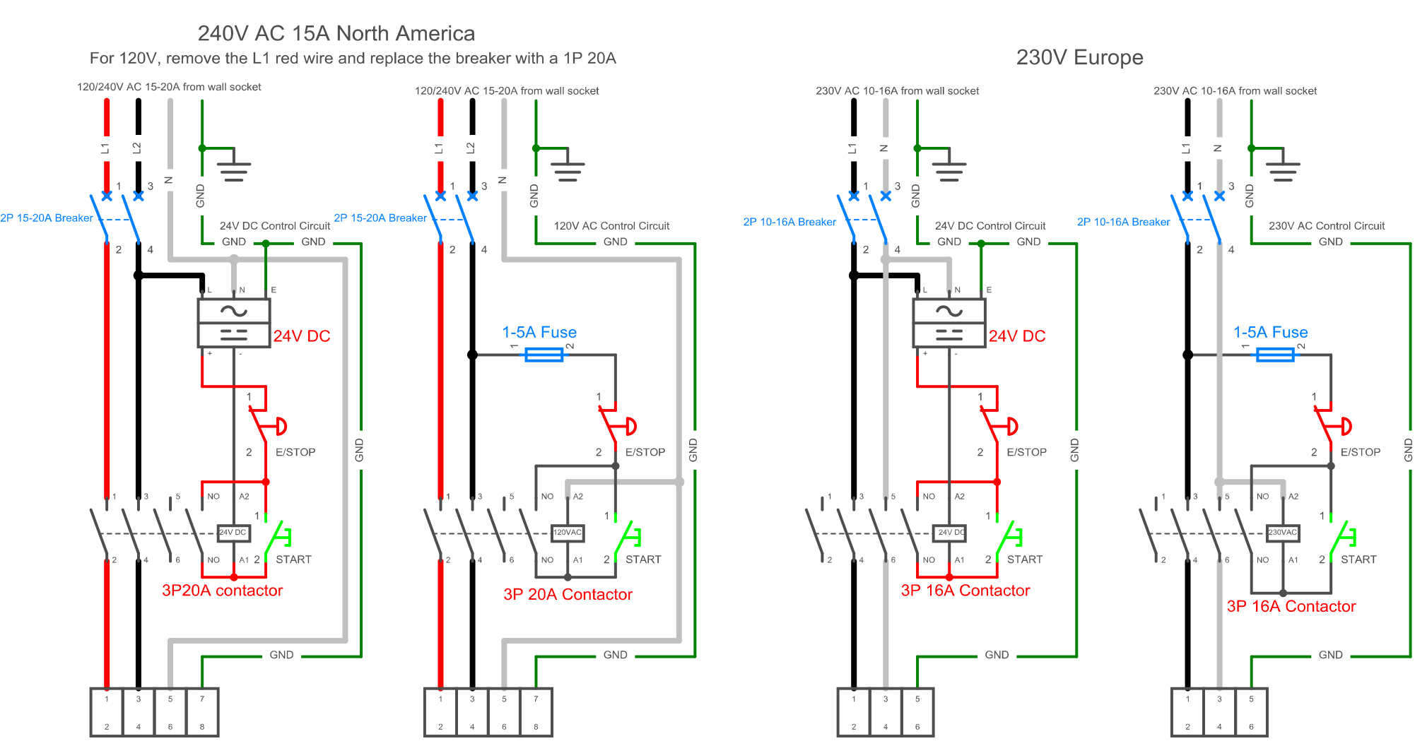
There are two different versions, depending if you want to connect the main power source to the contactor directly, or if you want to use the 24V PSU
¶ Contactor with main power source
In this scenario, you connect the main power source directly to the contactor coil. You'll need a contactor with a 120V AC / 240V AC / 230V AC coil. You'll also need an additional 5A fuse because the auxiliary poles usually only accept low voltages.
¶ Contactor with a 24V PSU
You'll connect the 24V DC output on the PSU to the contactor coil. In that case, you'll need a contactor with a 24 DC coil.
¶ General worflow
As you can see in the above schematic, your contactor can be wired in two ways.
- main poles : the main power source will be plugged to 2 poles
- coil:
- the coil will be directly connected to the neutral wire (in case of a 120V / 230V contactor) or the negative wire (in case of a 24V DC contactor)
- on the other end of the coil, you'll have an E-stop button and a NO momentary switch wired sequentially.
- NO auxiliary pole : it will be connected in parallel, between the E-stop button and the NC momentary switch.
¶ Start of the CNC
By default, the contactor is open, and the poles are not connected.
The operator will push the start button. This will close the connection to the coil, closing the connection to the main and auxiliary poles.
¶ Default ON state
When the operator releases the start button, the circuit going through the start button will open.
However, as the contactor is now closed, the auxiliary poles will also be closed, closing the circuit to the contactor coil.
As a consequence, the contactor stays closed.
¶ Stopping the CNC
If the user pushes the E-stop button, the circuit to the coil through the auxiliary pole will open. The contactor will open, opening the connection between the main and the auxiliary poles.
As a consequence, the main power source will be cut, stopping all equipment behind the contactor.
¶ Driver
For grblHAL2000 users, there is a separate wiki section for wiring the GRBLHAL2000
¶ Breakout board to stepper driver
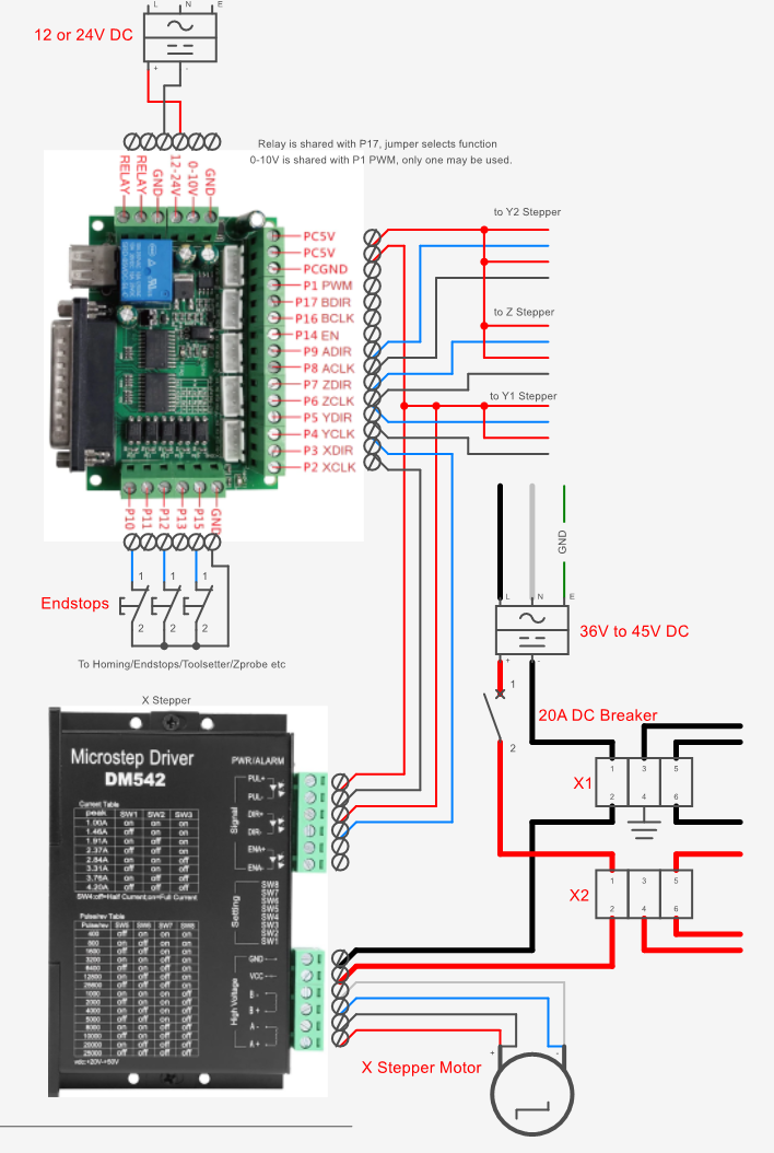
Drivers are connected to both the breakout board and the stepper motors.
You'll need to connect :
- 5v from the breakout board to both
PUL+andDIR+pins - the
X/Y/Z/A DIRpin from the breakout board to theDIR-pin on the stepper - the
X/Y/Z/A CLKpin from the breakout board to thePUL-pin on the stepper
The name of the pins are different for each axis :
XDIRandXCLKfor X driverYDIRandYCLKfor the first Y driverADIRandACLKfor the second Y driverZDIRandZCLKfor the Z driver
Wire DIR+/- pins and PUL+/- with twisted pairs, to help
Also, do not "daisy-chain" drivers. In plain English, do not connect wires from one driver directly to another driver. Always connect 5V to the breakout board.
¶ 36V - 45V DC PSU to stepper driver
You can plug the 36V - 45V DC PSU to the stepper driver like so :
- Positive from the PSU to the
VCCpin on the driver - Negative from the PSU to the
GNDpin on the driver
¶ stepper driver to stepper motor
Plug the two coils A+ / A- and B+ / B- to the stepper motor.
If you don't know which wire is connected to which coil, connect two wires on the motor and try to rotate the shaft. If it becomes harder to rotate the shaft after the two wires are connected, then the two wires are connected to the same coil.
Note: To reverse/chage the direction the stepper mootor spins you can switch the A+ and A- wires.
¶ VFD
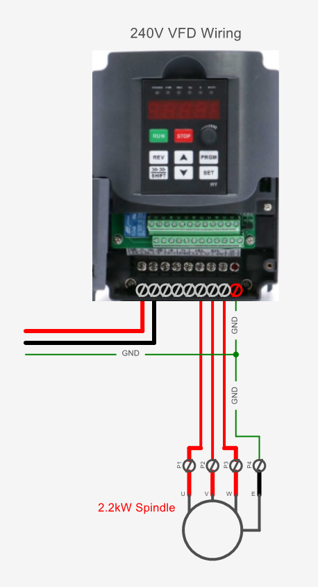
Example of Huanyang VFD wiring. Refer to your VFD manual for correct wiring of your specific VFD.
Also see VFD for more specific wiring information.
¶ Contactor to VFD
The main power comes from the contactor. It's important because you want to cut the power to the spindle as soon as the E-stop has been pushed.
Wire the live, neutral and ground.
¶ VFD to spindle
Wire 4 wires from P1, P2, P3 and GND respectively to U, V, W and E on the spindle. Use a double shielded (foil+braid) VFD cable for this connection, as you don't want interferences for that connectivity. The shield is connected at both ends.
Best method: Run the VFD cable continuous from VFD directly to spindle without any connectors between. Use a split plate and rubber grommet or cable gland for entry into the enclosure. Terminate the shield at the ground screw or dedicated shield screw on the VFD (if available)
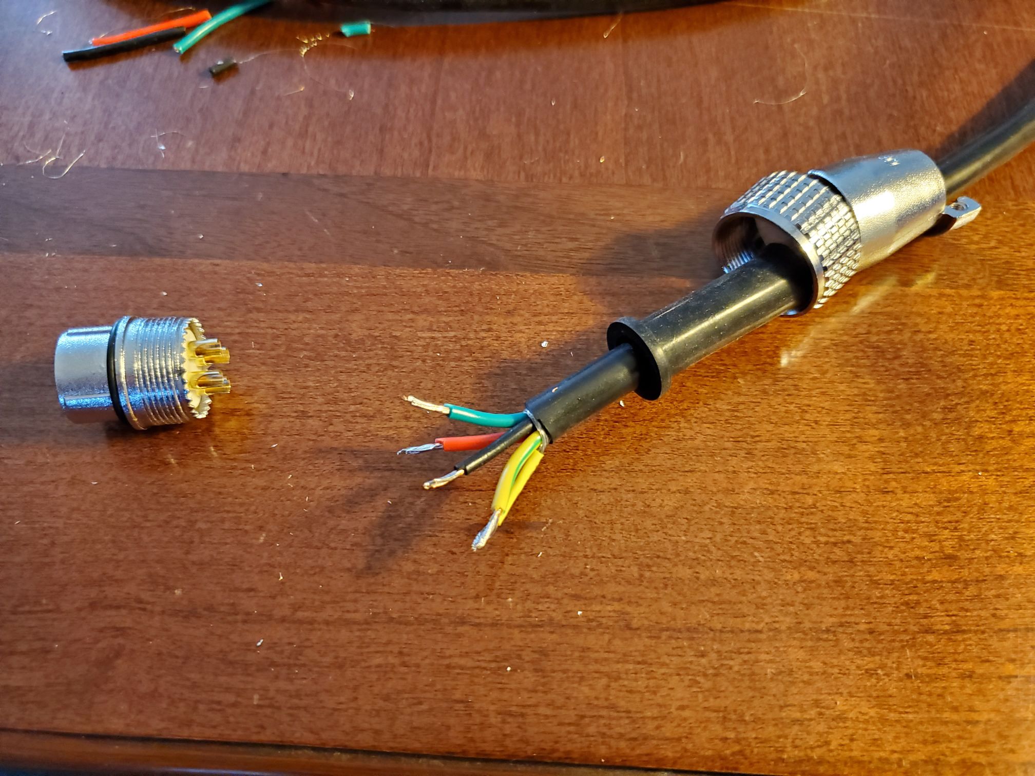
If you require a midpoint disconnection means, isolate the shield from the enclosure and connector by twisting into a wire and using shrink wrap, and connect to a separate pin from the ground wire to maintain the shield over the full length of the wire. The shield needs to continue from enclosure to VFD.
Twist the braid shield into a strand and use a bit of heat shrink to keep it together, then solder to pin 4 with the ground wire.
See the Belden Inc. video demonstrating how to terminate foil/braid shielded VFD cable directly to the VFD:
Belden Inc.
For more information about why shielding is important:
southwire1
southwire2
¶ Wire length, sizing and management
You'll need various wires to connect all the electronics. This section will detail the needed diameter and length.
¶ Cable sizes
¶ Main AC power (110V / 240V / 230V)
The size of the wire you'll using for the main AC power will be dependant of the current of your installation.
- for 30A, use 10AWG or 6mm²
- for 20A, use 12AWG or 4mm²
- for 15A, use 14AWG or 2.5mm²
Use 3-cores, stranded wires cable.
¶ PSU to components
Use 2 cores, unshielded 16AWG (1.5mm²) or 18AWG (0.75mm²) stranded wires cable.
¶ stepper driver to stepper motors
Use 4 cores (or 2 x 2-cores cables) shielded 18AWG (0.75mm²) stranded wires cable.
¶ breakout board to stepper driver
Use Cat6 cables for this connection. Select twisted pairs for each connection (DIR+/- and PUL+/-).
¶ VFD to spindle
Double-shielded (braided and foil) 4-core VFD wire. Shield and ground needs to be terminated to both VFD and spindle.
- 2.2kW 120V spindle use #16 AWG or 1.5mm² VFD cable.
- 2.2kW 220V spindle use #18 AWG or 0.75mm² VFD cable.
- 1.5kW 120V spindle use #16 AWG or 1.0mm² VFD cable.
- 1.5kW 220V spindle use #18 AWG or 0.75mm² VFD cable.
¶ limit switches/sensors
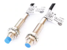
Use 22AWG (0.34mm²) unshielded cable, stranded wires, 2 cores for switches, 3 cores for inductive sensors.
You can also use Cat 5 or Cat 6 cables for this. (only patch cable because it has fine strands and is designed for flexing, not solid copper cable for installation)
The Ali kit may come with (5) LJ8A3-2-Z/AX. Only four are really required, so the fifth is a spare. The four are: X max (or min), Y1 max (or min), Y2 max (or min) and Z max.
The wire colors are brown, blue and black:
brown is +
blue is -
black goes to break out board pin
Check if there is a wiring diagram on the sticker of the sensor.
Note: The sensor is in the blue tip so be sure to have the metal (or aluminum) come close to the top of the tip, not the along the side of the sensor.
See https://wiki.printnc.info/en/mods#inductive_sensor_mounts for more info
See https://wiki.printnc.info/en/controllers/linuxcnc/bob for Break Out Board and LinuxCNC
When homing testing with the sensor, you can run the hal meter, select the input sensor and see if it flips from true to false (or vise versa) when the sensor gets close to metal.
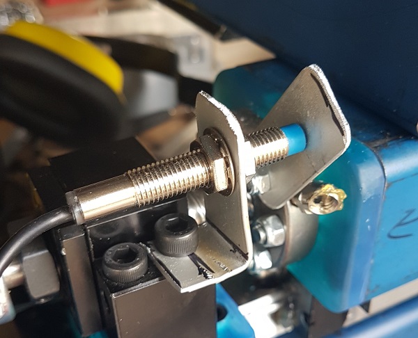
Quick amd Dirty sensor mount.
Drill and fold some aluminium strip just to get started if you have not got a better way to mount them.
There are good/better mounts in Mods and on the Discord.
¶ Cable lengths
¶ Stepper motors
The length of your cables depends on your actual machine size and the distance between the electronics enclosure and the point where the cables enter the machine. For the stepper motors, you can calculate the lengths of the four cables with this formula:
(distance from controller to rear corner of machine + 30cm)
 + (frameY + 30cm)           for Y1-Motor
 + (frameX + frameY + 30cm)  for Y2-Motor
 + (frameY + 60cm)           for X-Motor
 + (frameX + frameY + 90cm)  for Z-Motor
According to this formula, the Y1 motor has the shortest cable length. The Z motor has the longest cable length.
¶ Spindle wire
The length for the spindle wire is:
(distance from controller to rear corner of machine + 30cm) + (frameX + frameY + 90cm)
Add further length if you don't terminate the wire at connectors at the enclosure outside but wire directly inside to the drivers/VFD
¶ Cable management (or how to avoid breaking wires)
Wires connected to the motors, spindle and proximity sensors are typically bundled into a cable chain (provided with the Ali express kit). When mounting the chain to the PNC frame, one should strive to maximize bending radii to prevent wires from breaking.
It is highly recommanded to check the vendor's recommandations for your cable minimum bend radius (MBR). This value may be indicated directly on the cable (e.g., MBR8: 8x the cable diameter).
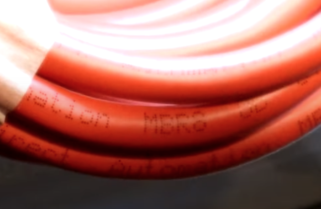
If you cannot find information from the vendor, you may use the table below to figure out the minimum bending radius for your cables.

For multiple conductor cables like those used on the PNC, the minimum radius of the drag chain should be at least 7x the overall cable outer diameter or 12x the diamter of each individual wire, which ever is greater. The table below provides MBR tabulated for 4-conductor shileded cables from gauge 15 to 22. These values are not guaranted to work for you cables but should give you the bare minimum MBR values to aim for when installing your drag chains.

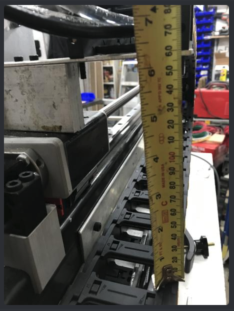
For reference, connecting the Y cable chain directly to the Y roller leads to a radius of 60mm, which can cause issue for gauges less or equal to 16 (!!! warning 2.2kW/120V spindle users !!!).
To increase radius, it is recommended to move the connection points as high as possible from the drag chain "floor" using either 3D printed mouting brackets (see Wiki/mods) or machined ones as shown below (credit DavidR8).
¶ Things to watch out for:
- Do not "daisy-chain" your wiring. In plain English, do not connect wires from one component directly to another component. Always add a wire from the source to the destination component. For example don't just run one 5V wire from the BOB to the first driver and then from there on to the second, third... but use one wire for each signal from the BOB. Use wago clip, terminal blocks or some other method.
- Many clamps or terminal blocks are made for solid core wire. To insert stranded wires the end must be terminated with ferrules.
- Tinning wires going under a compression plate or screw is a really bad idea (such as a terminal block, break out board connection/ or stepper driver connection) The tin can creep under load. Use ferrules instead.
- Tinning stranded wires makes them non flexible and prone to cable breaks. Avoid soldering wires at places where they are exposed to continuous bending and use crimped connectors instead