¶ Warning: factory reset does not set the parameters for your VFD for spindle use. If you reset your settings, you must the enter all settings again. Failure to do so can damage your spindle or VFD.
There are many flavors of variable frequency drives (VFDs). Many builders use MODBUS RTU communication protocol over RS485 to control their VFD from their CNC controller, some of the documentation of this setup for the popular VFDs are on this page below. There are other models of VFDs that others have used that also have had profiles/plugins built for the popular controllers. If you choose a less popular VFD that has poor or incomplete documentation/manual, then it may be difficult to setup the communications.
The Huanyang HY series: /spindle_settings.pdf was a popular VFD. That is what is mainly documented.
However, Ali has started to ship the Yalang YL620 series VFD. (scanned manual)
¶ General Process for RS485/MODBUS control of your VFD from grblHAL or LinuxCNC
- Follow the instructions on this page to correctly wire and configure your VFD for manual control
- Make sure the VFD works perfectly when controlled manually via the panel of the VFD: start, stop, forward, reverse, RPM control and feedback
- Follow the platform-specific instructions to control your VFD via RS485: grblHAL VFD control, LinuxCNC VFD control
¶ VFD Startup Settings (Huanyang, HY)
This config is to verify the VFD and spindle using the front panel and some sane default config.
| parameter | value | Description |
|---|---|---|
| PD000 | 0 | Parameter lock, 0=unlock |
| PD001 | 0 | Use the front panel for easier debugging. (Set to 2 for RS485 control) |
| PD002 | 1 | Use the front potentiometer. (Set to 2 for RS485 control) |
| PD005 | 400.00 | Max operating frequency. (Note that this is PD005 - this setting dictates the maximum frequency limit that is used by the other frequency settings.) |
| PD004 | 400.00 | Base frequency. (Note that this is PD004, and is out of order, this is intentional) |
| PD003 | 400.00 | Main frequency. (Note that this is PD003, and is out of order, this is intentional) |
| PD006 | 2.50 | Intermediate Frequency. [Factory Default] |
| PD007 | 20.00 | Min frequency, for the VF curve. |
| PD008 | 220 | Max output volt, for a 220V spindle. |
| PD009 | 15 | Intermediate voltage on the VF curve. |
| PD010 | 8.0 | Minimum voltage. |
| PD011 | 100.00 | Minimum frequency, the spindle could overheat at lower speed and the spindle does not have torque at low speed. |
| PD014 | 8.0 | Acceleration time, can be lower for faster acceleration. |
| PD015 | 8.0 | Deceleration time, can be lower for faster braking. |
| PD070 | 1 | Sets analog voltage range to 0..5v - required if you want the full RPM range available on the front panel dial. |
| PD141 | 220 | Motor rated voltage, its 220 even in North America, the VFD will convert the 240V at the input in 220V at the output, as required. This is for the 220V spindle. |
| PD142 | 9.0 | Motor maximum Amp, its 9A for the 220V spindle. |
| PD143 | 2 | Number of poles, 2 for the 400Hz, 24000rpm 2.2kW stock spindle. |
| PD144 | 3000 | A value of 3000 = 24k RPM for a 2 pole spindle which is most commonly used. This is the RPM of the spindle with a VFD frequency of 50 Hz. |
| PD163 | 1 | For RS485. Inverter manual: Range 00 - 250, factory setting: 00 LinuxCNC: Set register PD163 (communication address) to 1. This matches the default in the hy_vfd driver, change this if your setup has special needs. |
| PD164 | 2 | For RS485. Inverter manual: Range 0 - 3, 0: 4800 b/s, 1: 9600 b/s, 2: 19200 b/s, 3: 34800 b/s; factory setting: 1 LinuxCNC: Set register PD164 (baud rate) to 2 (19200 bps). This matches the default in the hy_vfd driver, change this if your setup has special needs. Make sure this matches the baud rate specified in LinuxCNC VFD config. |
| PD165 | 3 | For RS485. Inverter manual: Range 0 - 5, factory setting: 0 LinuxCNC: Set register PD165 (communication data method) to 3 (8n1 RTU). This matches the default in the hy_vfd driver, change this if your setup has special needs. Note that the hy_vfd driver only supports RTU communication, not ASCII. |
| PD176 | 0 | Inverter Frequency Standard. Factory setting that can be observed but not changed. Factory setting is 0 (50Hz). No issues reported using with 60Hz input power. |
¶ VFD Startup Settings (Yalang, YL620-A)
This configuration is to verify the VFD and spindle using the front panel and a sane default configuration.
| parameter | value | Description |
|---|---|---|
| P00.01 | 0 | Motor controlled by dial on front of VFD |
| P00.13 | 1 | Locked (after changing settings) |
Or if planning on using the RS485 interface:
| parameter | value | Description |
|---|---|---|
| P00.01 | 3 | Motor controlled by RS485 |
| P03.00 | 4 | 19200 (or you can opt to use 9600, which might be a better option) |
| P03.01 | 10 | Id (defaults to 10) |
| P03.02 | 2 | 8 1 None |
| P03.03 | 3 | Deal with RS485 communication error (default is option “0” which “decelerate to stop”, but option “3” is “Non-Stop” |
| P04.03 | 3 | Sets VFD relay to run when the spindle is turning can be used for water pump power to only run while spindle is on |
Whatever communication options you select on the VFD, be sure to update/match in the vfd ini file (ex: YL620.ini).
¶ Wiring
¶ North America, 240V
This is the recommended setup due to the lower wire size required. A normal 120V 15A circuit does not have enough power for a 2.2kW spindle/VFD, only 1440W is available on a normal outlet.
A Nema 6-15 is enough to power the VFD and your stepper drivers, this outlet only requires a dual pole 15A breaker and AWG14 wires. This outlet allow access to both 120V phase in your electrical panel, with both of them, you can have a 240V device. Most of modern electronic will use directly 240V without modifications.
Your oven, dryer, water heater are already connected at 240V.
A video about 240V in North America
Connect each phase to R and S VFD terminals.
¶ Rest of the world
You probably have easy access to single phase 220V or 240V outlet. Connect live and neutral to R and S terminals
¶ Grounding / shielding
As a rule of thumb, Chinese products are always grounded incorrectly, so verify the ground before powering up equipment.
The ground of the input cable needs to be connected to the red screw labeled ground on the VFD. The input cable ground also needs to be connected to your enclosure. Since you probably need that ground connected to multiple devices, you can use some terminals to connected all of them in a star pattern.
The spindle shield and ground will also need to be connected on this red screw on the VFD.
- The spindle shield needs to be connected to ground on both ends (VFD and spindle). This is different from a normal signal shield, where only one end is connected to ground.
- A doubly shielded cable with an aluminium foil and a braid is preferable. To make a clean connection, cut the outer jacket, unbraid the braid and twist all the strands.
- Both the green/yellow ground wire and the braid need to be connected on the 4th pin.
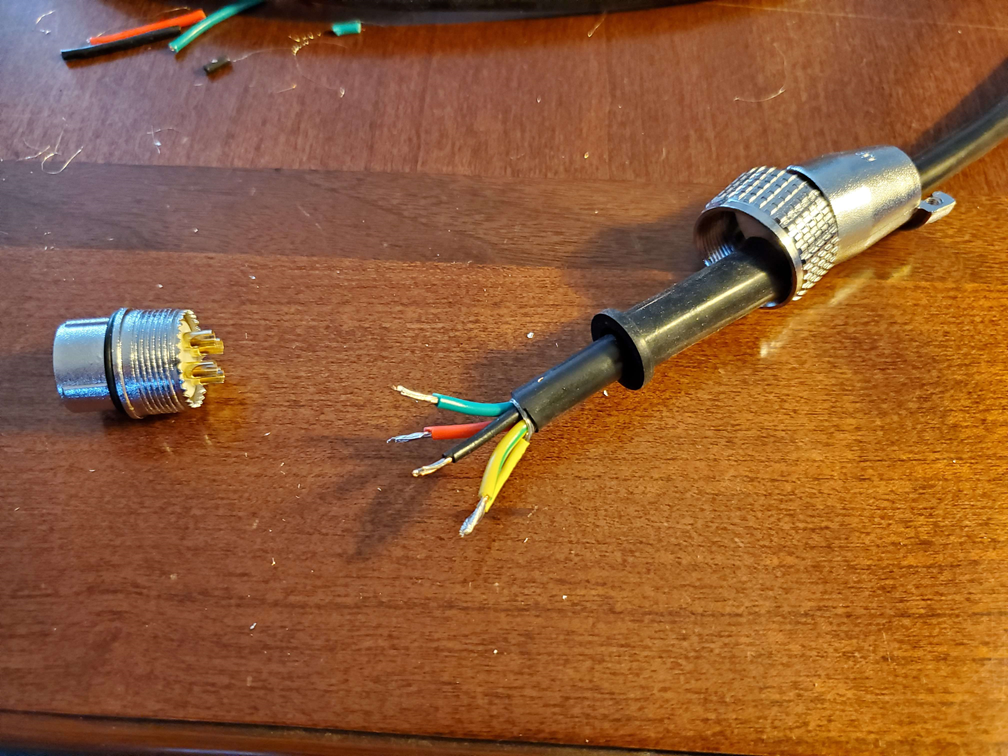
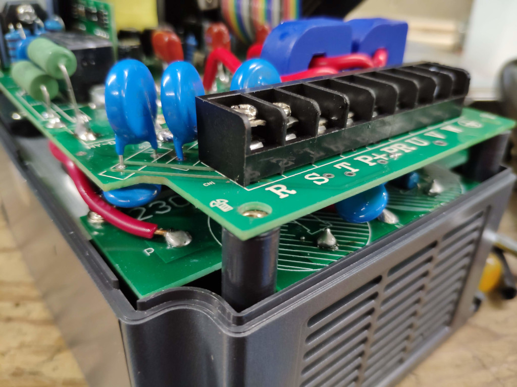
The screws in the plastic case in the lower left and right are not connected to ground. Do not use them for grounding - they are for holding the case together only.
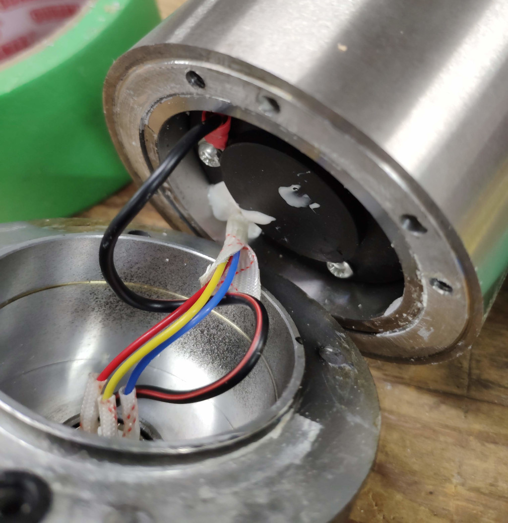
The spindle might not be grounded at the factory. You can verify if this is the case by either using a meter on continuity (beep) between pin 4 and the case of the spindle or removing the 4 screws holding the connector to the spindle and pulling on the connector.
If the 4th pin is not connected, you will need to open your spindle to add a ground wire to the case.
To open the spindle:
- remove the 4 hex screws and pull the top.
- There might be some silicone caulk holding the top, so hitting it with a rubber mallet might be necessary to remove the top.
- Solder a AWG18 wire to the 4th pin connector and
- connect the other end to the spindle case using a eye terminal.
- Clean the old caulk
- verify the O rings where the water will flow in the outer casing
- add some new silicone caulk and close it back
- Wait 24 hours for the caulk to dry before testing the water cooling.
¶ First startup
- Verify your water cooling loop by running it to check for leaks, keep it running while you are doing the setup.
- Wire the input of the VFD (not the output yet) and power up the VFD
- Configure using the startup settings
- Unplug power
- Connect the spindle to the output of the VFD. The ground pin of your plug should have continuity with the spindle metal case.
- Plug in your power, and verify the water flow. Set the potentiometer in the middle. Set the display to Hz on the VFD.
- Press on RUN button. Adjust the potentiometer to warm up the spindle at 100Hz. Let it run for at least 5 minutes, then ramp the speed up slowly every minute until you reach 400Hz. The spindle should draw about 1.5A to 2A, this value can be displayed on the VFD screen.
- By default, the spindle should spin clockwise, when you are looking at it from the top, If the spindle is going counter-clockwise, swap any of the 2 output phase, it will reverse the direction.
¶ Basic Settings (Huanyang)
¶ Control System
¶ 0-10V
Talking about that stuff here
¶ 0-5V
The spindle speed can be set via an analog 0-5V signal. For this to work the VFD needs to be configured with the correct voltage range as 0-10V is the default.
| PD001 | 1 | External source |
| PD002 | 1 | External source |
| PD070 | 1 | Voltage range: 0-5V |
A relay can be connected between the DCM and FORward pins on the VFD. The spindle will start when the relay is toggled and a voltage above 0V is applied to the FOR pin. The input of the relay is then connected to the spindle enable output of your controller. Alternatively the connection can be made with a jumper wire between the DCM and FOR port. However, using a relay is safer, as once the spindle is activated and a minimum speed has been configured the spindle won't turn off with 0V.
Changes to be made in GRBL are detailed on the GRBL page.
¶ Relay Control for Water Pump (Huanyang)
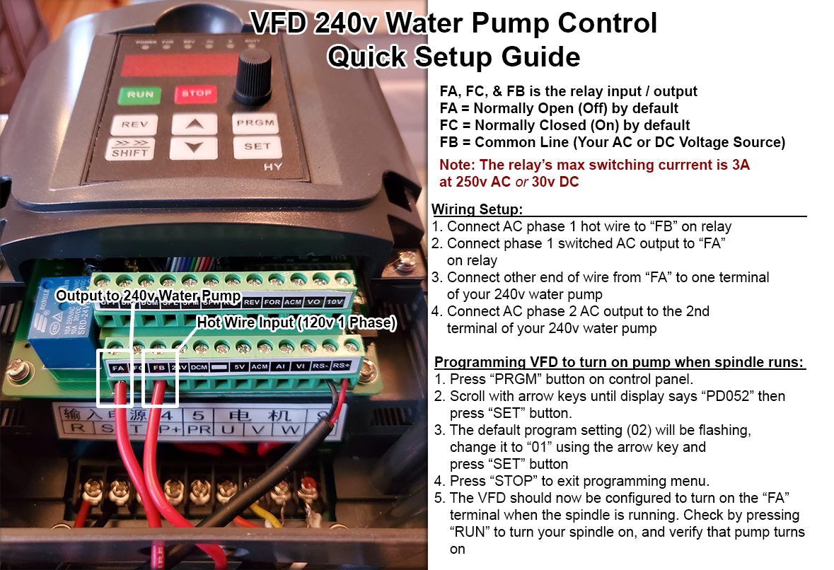
The HY02D223B (and similar models) VFD has terminal input / outputs to control and monitor various external devices.
- The “FA” “FC,” and “FB” terminals on the VFD control an internal relay.
- This relay has a maximum switching current of 3 amps at 250v AC or 30v DC, suitable for controlling smaller current devices (such as a water pump).
- FA is Normally Open (off) connection by default.
- FC is Normally Closed (on) connection by default.
- FB is the common terminal - This is where you will connect the power source to be switched with either FA or FC.
Please see below infographic for detail on programming VFD - Text will follow illustration:
¶ Wiring VFD Relay to External Device (Huanyang)
- Connect the power source to be switched into the FB terminal - In this example, we are using 1 phase in a 2 phase 240v AC power source.
- In terminal “FA” connect the wire that will go to your switched current
- Connect the other end of the wire coming from “FA” to your switched device - In this example, we are connecting to 1 terminal of a 240v AC water pump.
- Ensure your switched device has its other necessary connections in place to function when the relay activates - In this example, we make sure that the 2nd phase of our 240v circuit is connected to the 2nd terminal in the 240v water pump.
¶ Programming VFD Relay (Huanyang)
- Press “PRGM” button on VFD's control panel
- Use the directional arrow on the VFD panel to scroll until the display reads “PD052” - This is the setting that controls the relay. Press “SET” to select it.
- After SET is pressed, you will see a flashing number. This will likely be “02” which is the default setting for this VFD. Use the arrow keys to set the flashing number to “01” - After that press “SET” to lock in the setting.
- Press “STOP” to back out of programming for now
- The VFD is now set to close the connection (turn on) between FA and FB when the spindle is detected as running (more specifically, when the variable frequency output is active). This will make your connected device (240v water pump) turn on when the spindle runs, and turn off when the spindle is not running.
¶ Controlling VFD via RS485
The Huanyang and YL VFDs do not use the same communication.
¶ Huanyang
Connect the RS+ and RS- to A and B on a USB dongle.
¶ Basic Settings for Yalang and LinuxCNC
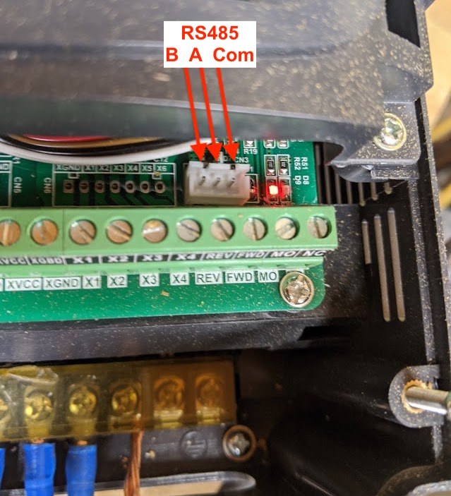
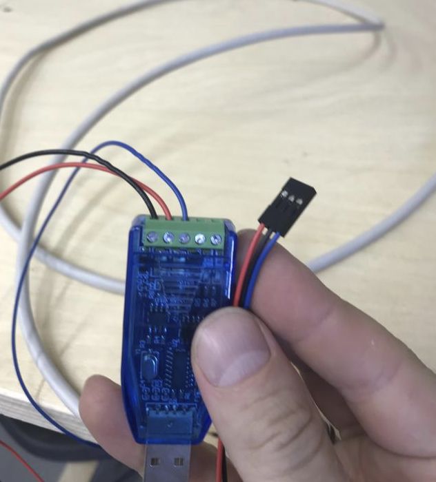
Connect the B, A, and COM pins on the white 3 pin JST-XH header above the screw terminals to a USB dongle. The docs show the pins as: B+, A-, and COM. One solution is to use VFDMOD
USB dongle seems to work best if it uses the FT232RL chipset for RS485
For this to work, you need to add the user that runs LinuxCNC to the "dialout" group. To do this:
1. run: sudo usermod -a -G dialout $USER
2. logout
3. log back in and confirm the user is in the group by running: grep dialout /etc/group and verifying your user is in that group.
Note: If you unplug the USB dongle and re-plug it back in quickly, it may create a newly numbered port. For instance, the first time the dongle may create /dev/ttyUSB0. Sometimes, it may create a /dev/ttyUSB1. Be sure to double check which one is being used by running: ls -al /dev/ttyUSB*
- Setting up a connection so the VFD connection wont change
- Run from command line: udevadm info --name=/dev/ttyUSB1 --attribute-walk
- To get the attributes for your USB dongle create a new USB rules file at /etc/udev/rules.d I called mine 99-usb-serial.rules
- Inside that file put in this (you need root to edit this file): SUBSYSTEM=="tty", ATTRS{idVendor}=="1d6b", ATTRS{idProduct}=="0002", SYMLINK+="rs485_dongle"
- Be sure to change the values to match your own vendor and product IDs
- Run: udevadm control --reload-rules
- To reload the rules run (change ttyUSB0 to yours if it show up as 1, 2, etc): udevadm test -a -p $(udevadm info -q path -n /dev/ttyUSB0)
- Read the lines and see if there are any errors reading the file
- You can now test with halcmd to see if it works with: loadusr -Wn vfd hy_vfd -n vfd -d /dev/rs485_dongle -p none -r 9600 show pin (edited)
[6:18 PM]
I've tested it and it's working, but I don't know if works after a reboot. I think it should though as the system should read the new usb rules and make the system link
[6:19 PM]
this way /dev/rs485_dongle or whatever you call it will stay the same regardless of if it changes ttyUSB number (edited)
[6:20 PM]
There are at least two options for LinuxCNC to communicate with the YL VFD: VFDMOD and mb2hal. See this page for help setting up RS485 communication with the YL-620a in LinuxCNC.
¶ Mitsubishi FR-D700 VFD RS485
Set the VFD up according to your spindle first.
Make a cable for PD-RS485 communication from a spare Ethernet cable, as FR-D700 uses RJ45 connector. Connect pins 3(RDA) & 5(SDA) to A on RS-485 dongle, pins 4(SDB) & 6(RDB) to B on RS-485 dongle, pin 7 is signal ground.
Settings for FR-D700 for control via Modbus RTU:
Pr. 77 Parameter Write selection-2
Pr. 117 PU communication station number - default is 0, set to anything but 0, this will be slave ID for Modbus
Pr. 118 to Pr. 120 set to match with mb2hal
Pr. 549 set to 1 to use Modbus RTU instead of Mitsubishi protocol
Use mb2hal component to control VFD via modbus http://linuxcnc.org/docs/html/drivers/mb2hal.html
Registers on FR-D700:
Stop, forward, reverse command: 8
Spindle speed set: 13
Spindle current output: 201
Spindle frequency output: 200
¶ CNCDrive AXBB-E board and YL620-A VFD Setup
For CNCDrive AXBB-E board and UCCNC with YL620-A series to setup control via PWM the terminal connections on the VFD are:
| VFD | AXBB-E | Notes |
| VI | AO1 | |
| GND | 5V0 | Use 5V0 on 5V Power Out not 5V0 on Port 1 |
| XGND | 24V0 | Use 24V0 common |
| FWD | Pin 7, Port 1 |
UCCNC settings are:
Spindle config screen: set "PWM Pin" to Pin 7, Port 1
I/O Setup screen: set "Spindle PWM -> analog ch" to 1
On the VFD:
Parameter 00.01 set to 1
Parameter 07.08 set to 3
¶ What the VFD displays when using RS485 (YL)
When you first turn on the VFD, the VFD display should show “F 00” flashing and the “FOR” light solid. (Note: If you are controlling the speed via the knob, then it will just be a solid “F 00” on the display.)
When you start LinuxCNC, and press the eStop button in LinuxCNC, the VFD display will sill show the same as above.
When you press the “power on” button in LinuxCNC, you should hear a click. (possibly from VFD, not sure)
When you press a “turn spindle” button, you should see the VFD display “F 00” solid, the “FOR” light should be on as well as the “RUN” light should be on.
When you press the “+” to increase speed, the display should change to something like “F 10.0”.
Be sure to press the “power off” and eStop buttons in LinuxCNC before closing LinuxCNC so the VFD behaves like the above. In other words, if you just click the “X” in the top right corner or just quit LinuxCNC, it may not reset the comms with the VFD.
When you hit your eStop button and power is “cut” from the VFD, you will see “ER 10” flashing. That is expected as there is no more power to the VFD. After 20-30 seconds, the VFD will be fully drained and the display will completely turn off.
¶ Calculating RPM from Frequency
Use the formula
RPM = 60 * Frequency
to calculate the RPM. For instance, the YL VFD goes up to 400 Hz (shown as “F 400.0” on the display) goes up to 24,000 RPM.
¶ Frequently Asked Questions - PrintNC - VFD/Spindle
¶ Q – What is the lower end of the RPM range for the spindle?
@logan: For wood it probably won't make as big a difference spindle vs router. But for metal being able to change the speed on the fly is a big deal.
You can run the spindle down to 6k rpm but as soon as it bogs down a little it'll lose a lot of torque and stall. I keep mine at 8k minimum so I can hear it starting to load and pause it and adjust some things.
For aluminum I'm running 22k for the endmill and 12k for drilling I think. It pulls out like 2-3" long spirals when drilling the first 3mm, then I just do 1mm pecks with full retracts to clear the chips.
¶ Q - Is serial communication with the spindle preferred over voltage control?
gerrg said: yeah because it gives some sort of feedback from the vfd
¶ Q – Any spindle setup best practices for the water cooling?
@Noot Few things I learned today: A flow indicator for coolant hoses is very important, because it helped me notice that I had a small clog somewhere in my loop. This was probably a piece of sawdust, or piece of plastic from my 5gal pail when I drilled for the bulkhead barbs.
I'm thinking this might be a common issue that I wouldn't have noticed without the flow meter (potentially damaging the spindle). So I put my pond pump in a nylon sock from the wife as a filter. So far is working really well, and nice insurance if I'm not watching for problems
I do have a lid on my pail, but even then there always a chance something will make it in there. Not sure how small the coolant channels are in the spindle