When you're first learning to use your machine it can simplify things to manually control your spindle speed and start/stop via the buttons and potentiometer on the front panel.
Once you're comfortable with the process of setting up and running a cut, it's a great quality of life improvement to have the machine take control of the spindle for you. grblHAL boards generally support RS485 (modbus) control, and/or analog voltage (0-10v). RS485 is the most robust as it allows the VFD to communicate current speed back to the board, whereas with analog control the system just assumes the spindle has reached the correct speed.
For an overview of the required VFD concepts, settings and wiring, check out the Electronics/VFD page.
¶ General Process for RS485/MODBUS control of your VFD
- Make sure the VFD works perfectly when controlled manually via the panel of the VFD.
- Connect to the controller, select the appropriate VFD driver and make sure that IOSender displays the correct RPM when you control the VFD manually.
- Set up the VFD for RS485 control (PD001=2, PD002=2 for HY, check your model documentation for specifics), make sure that the controller can drive the VFD
- Debug issues with steps 2 and 3.
¶ GRBLHAL2000/Flexi-HAL specific hardware setup for 0-10V control
The GRBLHAL2000 and Flexi-HAL both have a 3-pin jumper (labelled SPIN POWER) to connect either the 5V or 12V onboard (regulated) power to the analog spindle section.
If you're using 12V rather than 24V as DC power for the board, the onboard regulator for the analog spindle control section won't quite reach 10V, so this jumper should be removed and 12V should also be connected to the SPIN POWER input.
¶ Huanyang (HY) VFD Setup Guide
Here is a video showing how to program the HY 2.2Kw VFD. https://youtu.be/ZOdCpw7xnQA?t=57
To get the RS485 connection working with the HY VFD, you have to wire it up correctly, and change some settings.
¶ Wiring
Connect on the GRBLHAL2K side RS485 (A & B) and on the VFD side connect to RS+/RS- (A to RS+ and B to RS-). If the VFD is connected correctly when you switch ioSender's grbl settings Spindle > Default Spindle to VFD Spindle you will see both the red and green RS485 communications LEDs flashing
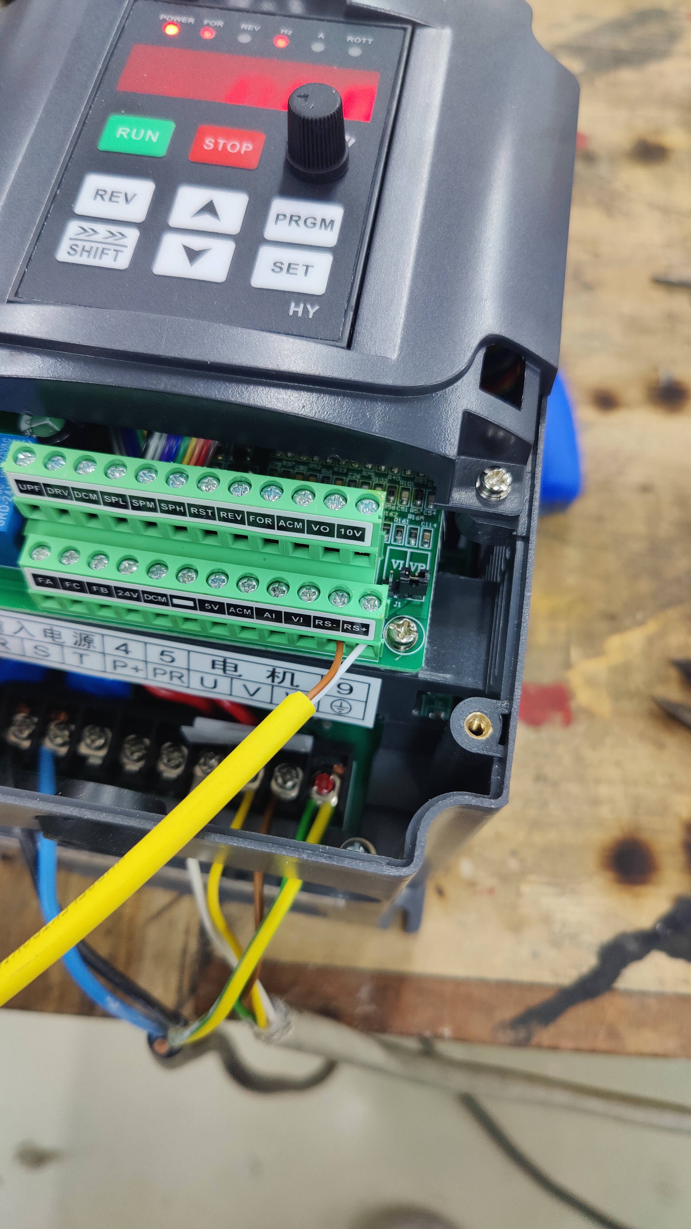
Setting up ioSender and the HY VFD
- in the VFD, configure the following settings
PD001 = 2
 #source of run commands = external terminal
PD002 = 2
 #source of operation frequency = external terminal
PD163 = 1
 #communication address for inverter = 01
PD164 = 2
 #BaudRate = 19200
PD165 = 3
 #Communication Data = 8N1

 PD052 = 1
 #for the automatic waterpump on FA/FB
- in ioSender, set:
- Spindle:
- Max RPM to 24.000rpm
- Min RPM to 6.000rpm
- Spindle on Delay to 30s (to be safe, this is the time IOSender waits, and then checks the Spindle Speed, if your ramp on the VFD is faster, you can change it to the max time, it takes until the Spindle hits 24.000rpm). In IOSender 'Spindle on Delay" can be found under Safety Door.
- Default Spindle: Huanyang v1
- Spindle:
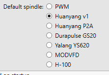
- ModBus:
- Baudrate:19200 (with a lower baudrate, the feedback doesn't work)
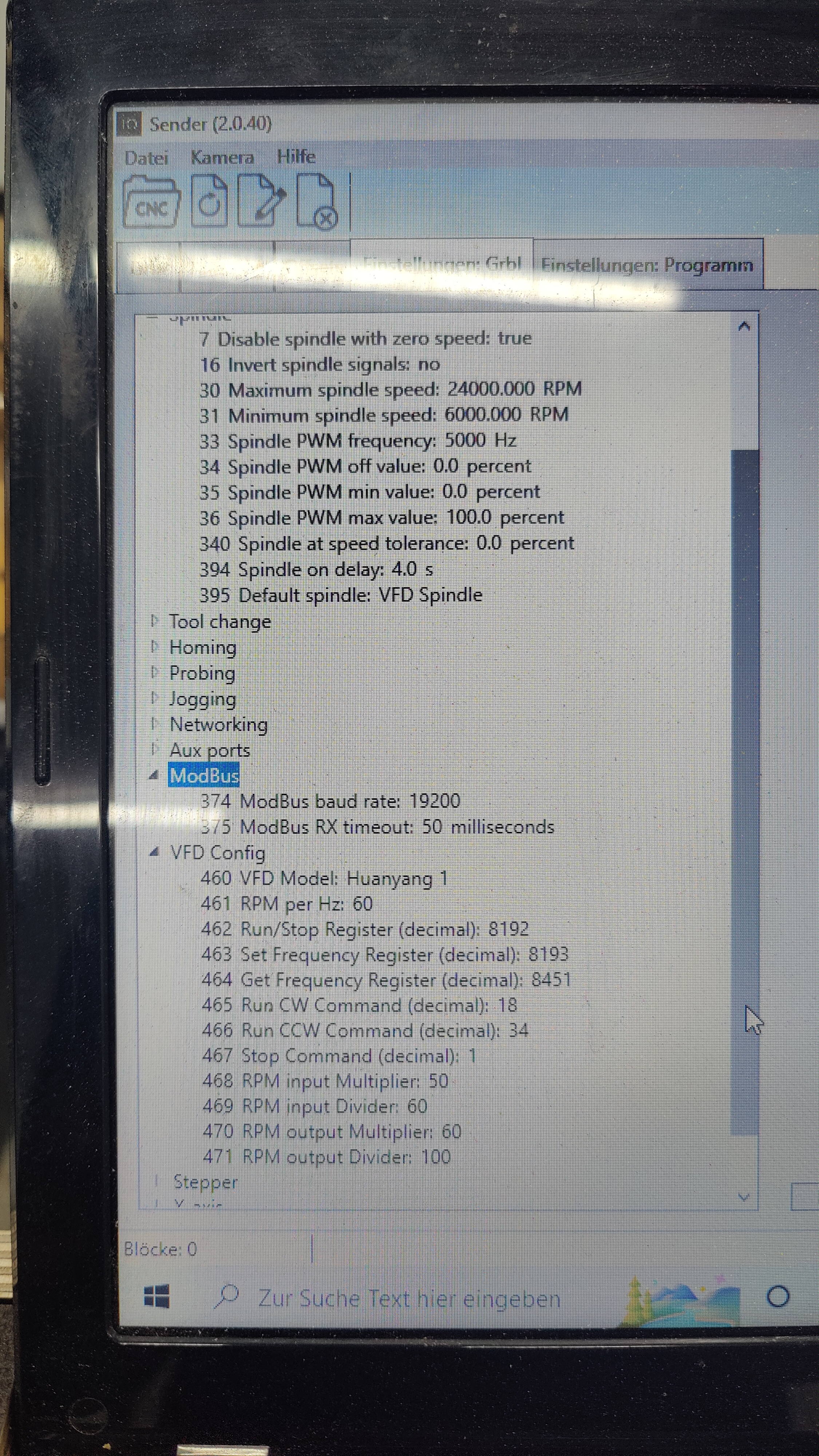
Now in IOSender, send M03 S6000; this should turn on the spindle, and you should be able to see feedback RPM on the right side of IOSender.
¶ YL-620A VFD Setup Guide
¶ Connect Power to the VFD:
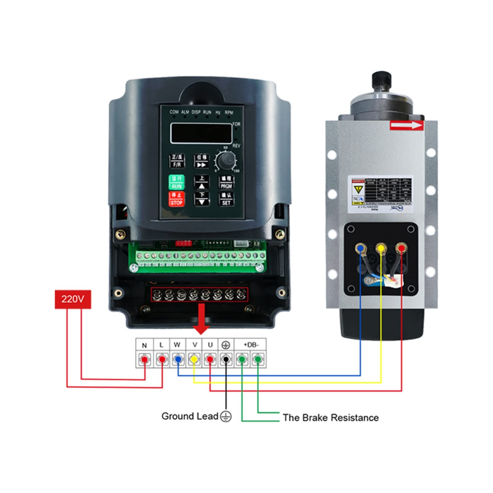
First connect the power to the VFD.
L = Live, N = Neutral. Also be sure to connect Ground. 110v and 220v both use the same terminal screws shown below.
REMINDER! MAKE SURE THE POWER IS OFF WHEN CONNECTING MAINS POWER! SAFETY FIRST!
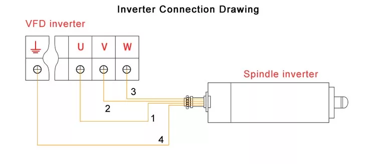
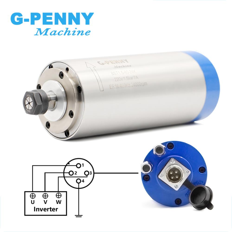
Also connect the spindle UVW wires as shown below.
Power on the VFD and then continue with the configuration.
¶ Getting IOSender to talk to the VFD using Analog Voltage
If you want IOSender to tell the VFD when to turn on, and what speed the spindle should be, we need to do some additional wiring, and some additional setup. “Analog Voltage” (0-10v) is one way to do this, and “RS485” is another. Either way works! This section is for the Analog Voltage option.
There’s three parts to this:
- Wire the GRBLHAL2000 board to the VFD
- Change some parameters on the VFD
- Change some parameters in IOSender
¶ First, the wiring. Just follow this diagram. The connections don’t make much sense right now, and that’s ok.
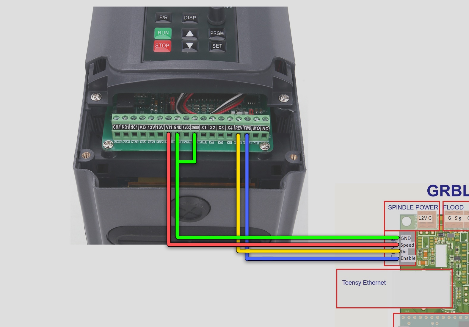
¶ *Note: It is recommended to use Cat5 cable for this connection. It makes a big difference! Use 1 pair for forward/reverse and a second pair for ground/pwm.
¶ Next, let’s configure the VFD. We need to change a couple things.
Here is a video showing how to program the YL-620A VFD: https://youtu.be/gKczHxuwvgQ?t=62
Latest YL620A (YL-620a) original color manual is found here./yl620manual.pdf
Here is the discord forum post for discussion and questions on this topic should you need more info or ask further questions: https://discordapp.com/channels/648972213734604807/1053441989548441631/1053441989548441631
We need to tell the VFD where to look for commands in general.
- Set P00.01 to 2, so it knows to look at these wires for input instead of the VFD buttons.

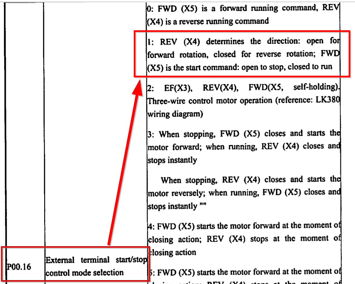
We also need to redefine what the FWD and REV terminals do.
- Set P00.16 to 1. Now, FWD means “start/enable” and REV means “direction”. Just like on the GRBLHAL2k board!
We also need to tell the VFD where to look for spindle speed commands.
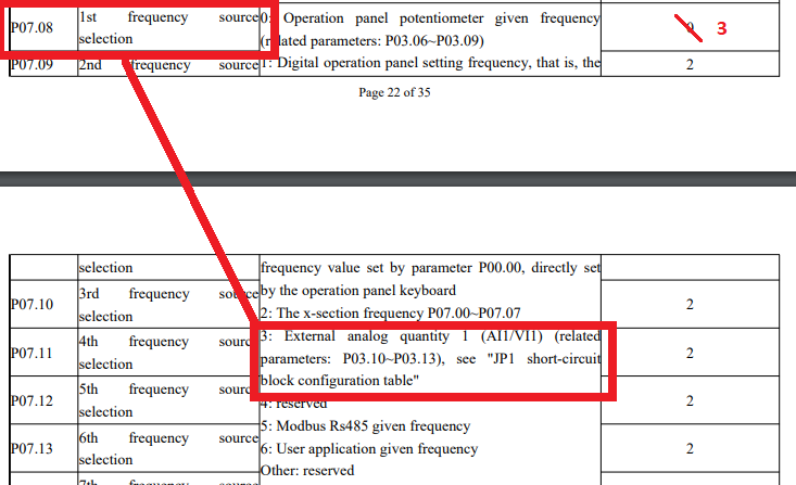
- Set P07.08 to 3. This tells the VFD to look at the VI1 terminal rather than the knob on the VFD panel.
- P07.08 must be set to 3. Not 1. #3 = External analog quantity 1 (All/VI1) (related parameters: P03.10-P03.13), see “JP1 short-circuit block configuration table”. JP1 are the dip switches on the front PCB of the YL620a VFD. See below for correct dip switch settings.

- P07.08 when set to 3 is what enables the VFD to choose Analog Voltage as it's signal source. So use option 3.
- (As opposed to option 5 if you're using MODBUS RS485).
- (Or as opposed to option 0 if you're manually controlling the VFD with the dial on the front panel).
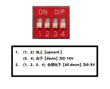
How to set the Dip Switches Correctly
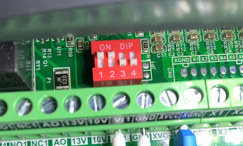
Set your dip switches as shown above: 1&2 on, 3&4 off for 0-10v. This is the factory default setting.
Set the Spindle Lower Limit to Begin at 60Hz:
Set P03.10 to 60. (Factory default = 3) The definition of P03.10 is “Analog input 1 Lower limit of AD value specification.”
The spindle begins spinning only after 60hz is displayed on the VFD display (If you set P00.24 = 1).
If you try to tell the spindle to spin any slower than with a 60hz PWM signal the motor won't spin.
Setting this to 60 ensures that the actual RPM of the spindle matches what is shown in iosender.
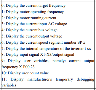
How to change what the VFD's front panel displays:
Set P00.24 to 1. If you want to see the motor's actual operating frequency. Or set it to one of the other options below. 0 = Default.
Finally, let’s tell IOSender what sort of commands to send, and from where.
- Just a couple settings in IOSender, and then we’re done!
- Set the maximum spindle speed (Usually 24000 RPM)
- Set the minimum spindle speed (Usually at least 1500 RPM) *Note: 6000 minimum is recommended.
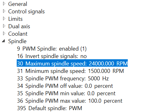
Later you might need to tune the PWM min and max values so that the RPM of the spindle exactly matches the RPM setting. * Note: This is already done above by setting P03.10 = 60.
Now you should be able to set spindle RUN/STOP/RPM directly from IOSender!
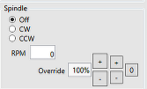
Just go to the iosender main screen and click the CW radio button, then enter an RPM value starting from 8000 or above.
Your spindle should begin to spin! Check that it rotates CLOCKWISE when looking at it FROM THE TOP.
To stop it, just click the OFF radio button. You can also increment up or down with the + and - buttons in 10% or 1% increments.
Quick summary:
You can just reset the VFD to defaults, do a power cycle and then just change these key settings if doing Analog Voltage: https://discord.com/channels/648972213734604807/741001353899409449/1048222826890539028
So the key settings are:
7.08 = 3
P3.10 = 60
P00.01 = 2
P00.16 = 1
There you go. Oh, and use a Cat5 cable - 1 pair for forward/reverse and a second pair for ground/pwm.. It matters. Spindle even sounds smoother with it. Twisted pairs FTW.
One other setting you might need to change is the default voltage. My spindle is a 110v so I had to change it from the default of 220v.

How to reset the YL620 VFD to factory defaults:
1. Press the PGRM button.
2. Use the arrow keys to change the bank to P00.13.
3. Set the value to 10.
4. Press the SET button.
4a. (Optional but recommended) Press and hold the STOP button and WHILE HOLDING THE STOP BUTTON press the Up Arrow. This will update the parameters in memory.
4b. (Optional but recommended) Press the PRGM key to exit the programming mode.
5. Cut the power to the VFD. Wait for the display to turn off. 10 seconds approximately. Wait another 10 seconds before powering back on to ensure the memory is cleared and it is reset to defaults.
It is now reset to factory default settings. You can confirm by comparing some of the settings to the defaults as listed in the manual.
HOW TO SET THE VFD TO THE CORRECT VOLTAGE. 220V IS DEFAULT.
P12.00 sets Motor rated current. Default = 5.0. Look on the side of your spindle. My 110v spindle says it's 8A. So I set mine to 8.0.
P12.01 sets Motor Rated voltage. Default = 220. I set mine to 110v.
P12.05 sets Inverter rated current. Default = 5.0. I set mine to 8A to match my spindle.
P12.06 sets Inverter rated voltage. Default = 220v. I set mine to 110v to match my spindle
The complete list of settings are printed in the YL620 manual. Posted at the top of this wiki page