¶ Inductive Sensor Mounts
¶ Parametric Min/Max Inductive Sensor Mounts - by Deime
Print additional screw/target holders to use as both min and max travel endstops. You can use double sided tape to position the drill guide on your steel sections, then mark the holes with your hand drill, remove the guide and drill and tap for M5.
Parts required:
- 1x Drilling Template
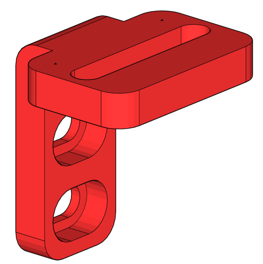
- 3x Sensor Mount (X, Y1, Y2)
- 5x Target Mount (X min/max, Y1 min/max, Y2 min)
- 5x M5 screws and nuts
|
|
|
[by RTFM]
If you find you need more adjustment than provided by the above mounts, try this one:
This one provides about 30mm of back and forth adjustment. You will need one M4 bolt with two M4 nuts. /sensor_mount_bottom.stl
(by ReduX_Hz)
/xy_inductive_limit_switch.f3d
(by Josh)
(by Mitch)
/y-axis_limit_sensor_front_mount_v3.f3d
Inductive sensor mounts variety pack:
(by J1mbo)
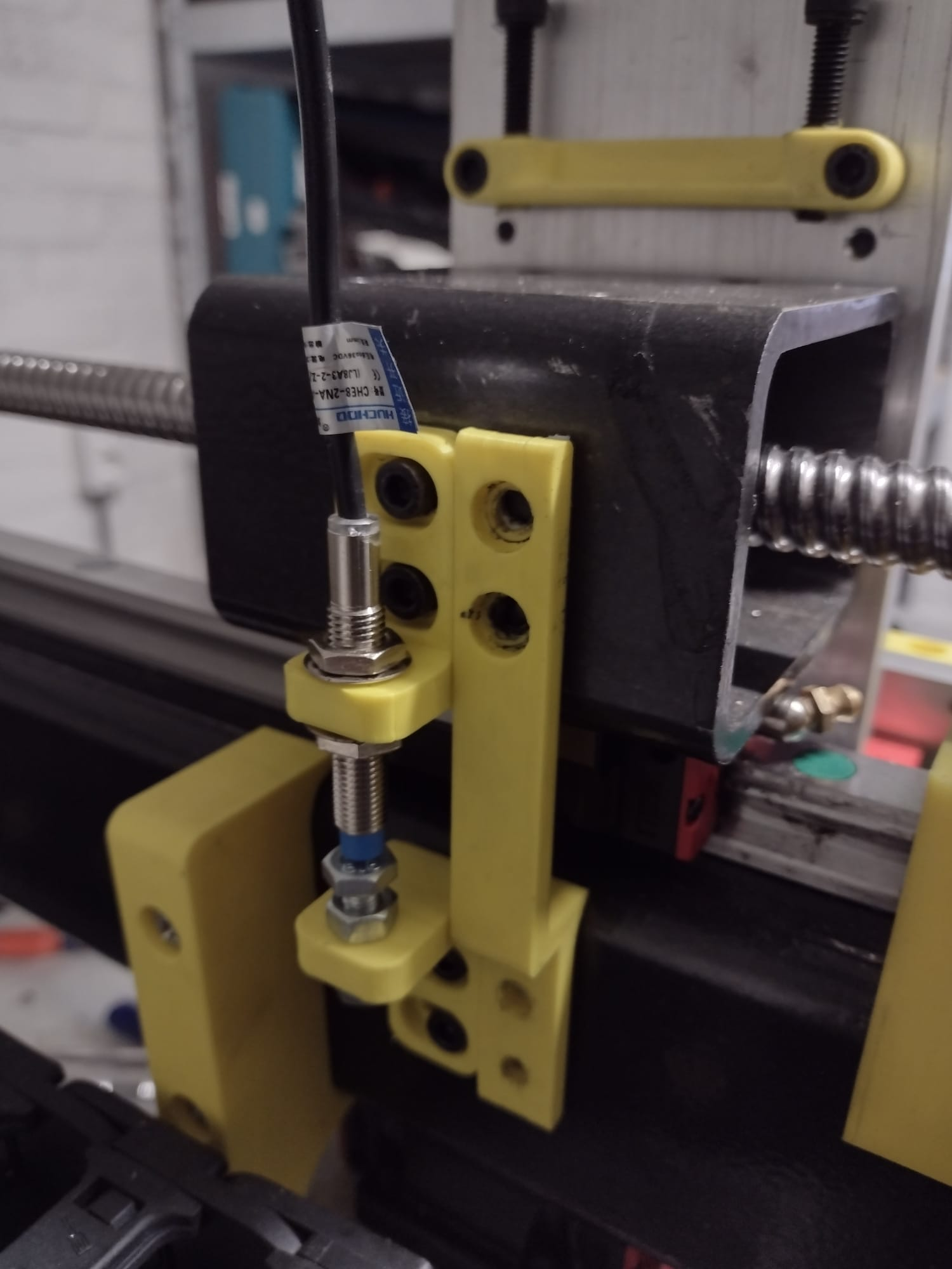
¶ Inductive sensor mounts with adjustable end position (Ikea Version):
(by Byrisch)
Please note that you need to consider the clearance to the cable chains! The model is not parametric and designed for 80x50x4mm steel with 9.25mm radius. Please modify to suit your steel. The metal plates are Ikea HACKÅS knobs.
¶ Roller-mounted adjustable 8mm Inductive Limit Switch Arm:
(by VanGoghComplex)
I wanted to design a simple, robust, adjustable limit switch mount for the X rollers which will non-contact trigger on the BK or BF block.
Hardware:
qty. 2 m4x16 socket head cap screw
qty. 2 m4 washer
qty. 2 m4x10 brass injection molding threaded insert
qty. 2 m5x16 socket head cap screw
The design includes a PrintNC-style hole locating template for marking holes on your rollers.


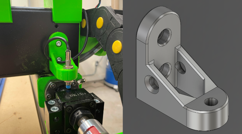
¶ Z Motor Mount + Inductive Switch Mount
This mod is to use 12mm sensor for Z. The kit supplied 8mm diameter sensors work with the stock Z motor mount.
¶ IHSV57 Servos
Be aware that the IHSV57 Servo Motors might only be a partial drop in for the NEMA23 stepper motors on the standard build. They come in different shaft lengths! The longer shaft is longer than that of the stepper but just fits using a PNCpro Mount. It's not guaranteed to work on printed parts.
Though they are rated at 0.6Nm this is the constant torque the motor can output. It can be tuned to allow 300% current draw for several seconds making the peak torque value closer to 1.8Nm.
¶ PNCPro
The PNCPro parts are Aluminium upgrade parts that a designed as replacements for the 3d Printed parts on your PrintNC. They are a space where builders can flex their design and CNC skills, as such they require a reasonable level of confidence and skill to manufacture
These parts must be viewed as a work in progress. Please carefully check parameters and measurements before cutting to ensure they correctly fit your machine
¶ Fourth Axis
You can add a fourth axis to your machine.
¶ Air blast
An air blast is a great addition to your machine if you often mill aluminium. It blows air towards your cutter for clearing chips and is normally also configured to supply small amounts of lubricant. This greatly decreases your chance of chip welding and will also improve the surface finish.
¶ Z-Axis
¶ Z2.1 Logan's Narrow Mod *Note: This design has been adopted for the stock design V3 available here: https://wiki.printnc.info/en/project-files
(by @Logan BC 🇨🇦)
Narrow Z with single-plate tramming on X/Y for Z rails and spindle, increases X travel by up to 35mm depending on build dimensions from stock 2.1
IMPORTANT: This design contains many parameters to customize to your needs. The default settings are intended to be milled from aluminum or wood, using an existing cnc, either mpcnc or earlier/stock version of the PrintNC. If you intend to create the Z plate with hand tools, you will need to set Modify> Change Parameters> ZFacePlateTrench to 0mm and bkCutThrough to 1mm to simplify the back plate.
Includes:
- Tram tension bolts on the Z plate with angle and spindle plate with printed or milled blocks to make adjusting tram easier
- optional second tram plate for non-standard spindle clamps
- optional second plate for supporting the BK10 block for thin Z plates - 8mm or 3/8" - set parameter bkCutThrough to 1
- keyhole ballscrew nut plates for upgrading from printed without a full rebuild
- single setting adjustment between 1610 and 2010 ballscrew nuts on the keyhole faceplates - set parameter BallscrewDiameter to 16 or 20
Additional Materials Needed:
4 -M6-8mm grub screws and 20 extra M5-20mm bolts (for tramming), 4 - M6-40mm bolts (for the clamp), 8 - m4-16mm (for ballscrew nut and sensor/switch mount)
¶ Z-Axis Motor mount with slotted nuts
(by @MortarArt )
This modification for the Z-axis motor mount mounts to both sides of the alu plate, to keep it more securely fixed, and has slots for nuts to help secure the motor.
¶ v2.1 Alternate Mount
(by @Tayas )
An entirely 3D-printed ball screw mount, as an alternative to or filler for an additional metal plate.
¶ MPCNC Tool Adapter Plate
(by @Tayas)
An adapter plate, useful to folks transitioning from an MPCNC (or other CNC) build who want to use existing tools and adapters.
https://www.thingiverse.com/thing:4565681
¶ Makita RT0700 Mount
(by @Tayas)
A version of the above mount specific to the Makita RT0700 router.
https://www.thingiverse.com/thing:4567056
¶ X-Y Axis
¶ Roller Plates
¶ 16xx and 20xx Parametric Keyhole Plates
(by @Logan BC 🇨🇦)
keyhole ballscrew nut plates for upgrading from printed without a full rebuild.
Mod (found within the narrow z mod)
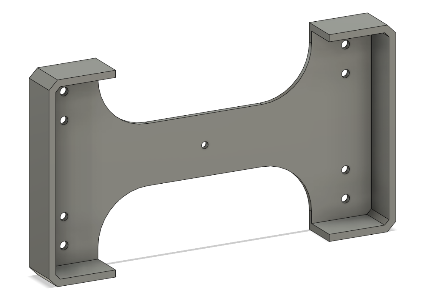
¶ X-Y Motor Mounts
¶ Parametric Motor Mounts for Nema23 or Nema24
(by @Logan BC 🇨🇦)
Added chamfers to the steel edge to minimize scratched paint, removed website from face as it didn't print clearly, added option for nema24.In the parameter notes are the dimensions for Nema23 and Nema24, doublecheck your motor to confirm, some Nema24 use 23 hole spacing.
¶ Nema23 / Nema24 compatible mounts
(by @MortarArt )
This modification includes some reinforcing, and mounting compatible with both Nema23 and Nema24 motors.
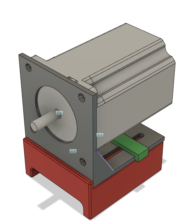
¶ Sheet Metal Motor Mounts
(by M0jo and Jake)
Utilizes the cheap sheet metal motor mounts available for <$1 on AliExpress. Allows you to run your motors hotter without worry of melting.
Current design need to have its height verified for better alignment. Verify all dimensions and print 1 copy, the initial design was too high for good aligment. The last operation in the fusion timeline was to reduce its height by 1mm to align it better.
The green guide is used to drill the motor bracket.
Note that this mount is longer than the stock mount. You will need to extend your gantry to allow this mod to fit.
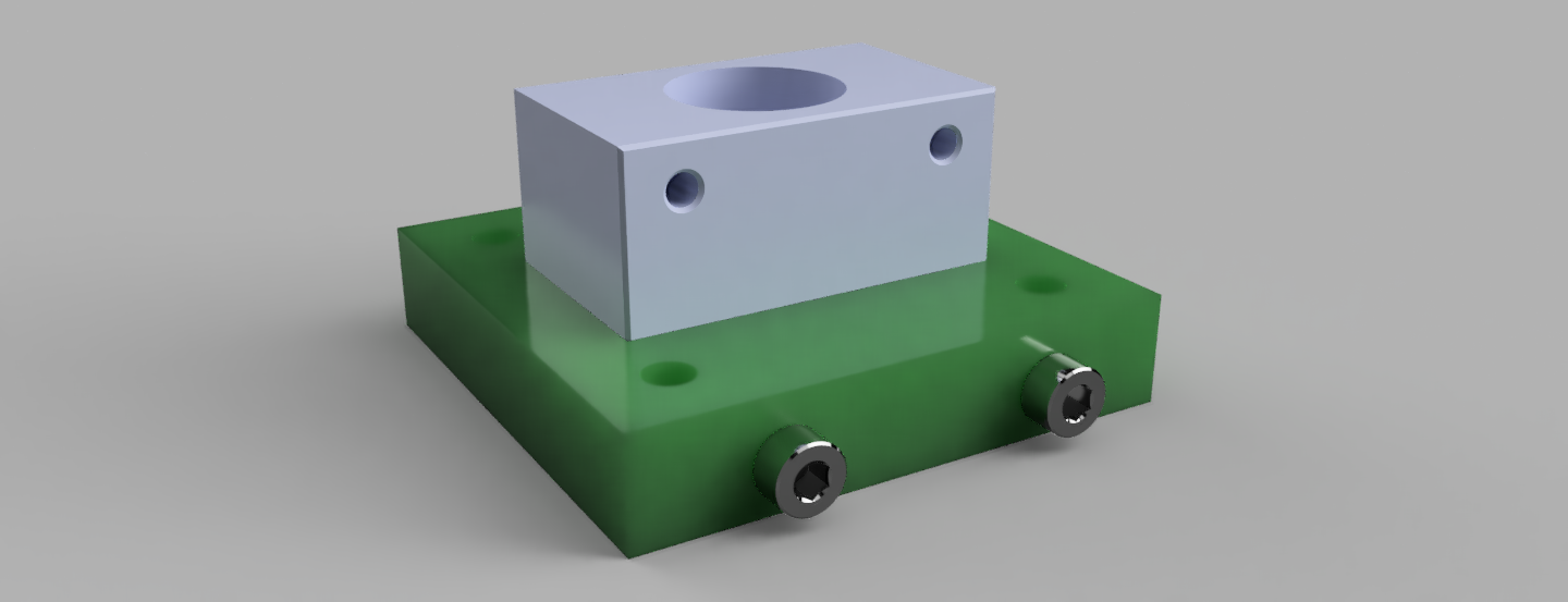
¶ BK/BF Mounts
¶ Simple BFBK Blocks
(by @Logan BC 🇨🇦)
Slightly increased Y travel when using alternate homing methods, either endstop switches or sensors.
¶ BK/BF12 Limit Switch Clip Mounts
(by @lauka)
BF12: https://a360.co/3hQSsfo
BK12: https://a360.co/2XhLrfR
¶ HM15-57 mount based on BF15
¶ Simple BFBK Blocks
(by @DZ /DZwijnenburg & @Logan BC 🇨🇦))
This is a HM15-57 mount for 2010 ballscrews. Based of the BF15 mod, I designed this for 80*50 steel. This is my first model so I don't know if it's parametric.
¶ Rotating nut Y axis for extended-length builds
(by rcw)
Several people have expressed interest in a cutting area large enough for a full sheet of plywood. Even very thick ballscrews would perform very poorly at the lengths needed due to ballscrew whip. For those that do not already have a CNC, a design philosophy similar to the PrintNC itself is essential - no precision tools should be necessary for the build. This approach uses a belt-driven rotating nut, NEMA23 motors, either 1610 or 2010 ballscrews, and dual carriages. It needs a minimum Y roller size of 75x75mm, so it will raise the gantry by 25mm and thus increase Z lever and decrease rigidity somewhat vs. the stock PrintNC. It uses an external angular contact bearing.
https://cdn.discordapp.com/attachments/1046013733572456499/1071851127802445824/rotating-nut-belt-drive.fcstd (Parametric FreeCAD file)
Parts (per Y roller - you'll need two sets of these):
- 75x75mm or 3x3" rectangular steel tube. The same radius considerations apply, however there is a workaround for 5mm thick roller tubes using the backside of a grinding stone in a Dremel.
- Y support frame tube: 50x75mm or 2x3", 5mm longer than the ballscrew.
- 50x6mm or 2x¼" steel bar, (2) 90mm lengths.
- NEMA23 motor, up to 100mm length
- Steel NEMA23 motor bracket
- 5206 Angular Contact bearing
- (12) M6x12mm button head bolts
- (4) M6x12mm bolts
- (4) M5x130mm bolts
- (6) M5x60mm bolts
- (6) M5x45mm bolts
- (5) M5x35mm bolts
- (4) M5x12mm bolts + one bolt for every 60mm of HGR20 rail
- (4) M4x8mm bolts
- (6) M3x35mm bolts
- HTD-5 belt (length depends on parameters chosen)
- HTD-5 pulley (diameter depends on parameters chosen)
- (3) Flush-mount grease zerks
- HGR20 rail, 100mm shorter than the ballscrew
Either the 1610-related or the 2010-related set of parts:
1610 ballscrews:
- 1610 ballscrew with SFU1610 ball nut, 258mm longer than desired travel, e.g. 2800mm for 2542mm Y cutting area
- (1) SK12 mount
- (2) SK10 mounts
- (1) RN12 Locknut
2010 ballscrews:
- 2010 ballscrew with SFU2010 ball nut, 283mm longer than desired travel, e.g. 2800mm for 2517mm Y cutting area
- (1) SK16 mount
- (1) 23x14mm 0.5mm thick brass sheet to make a shim
- (2) SK12 mounts
- (1) RN15 Locknut
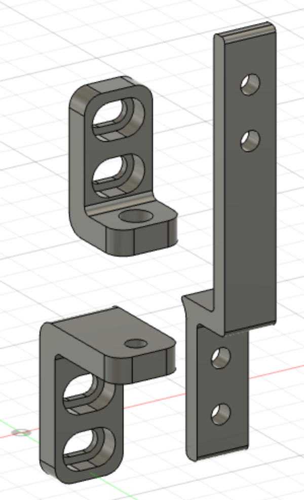
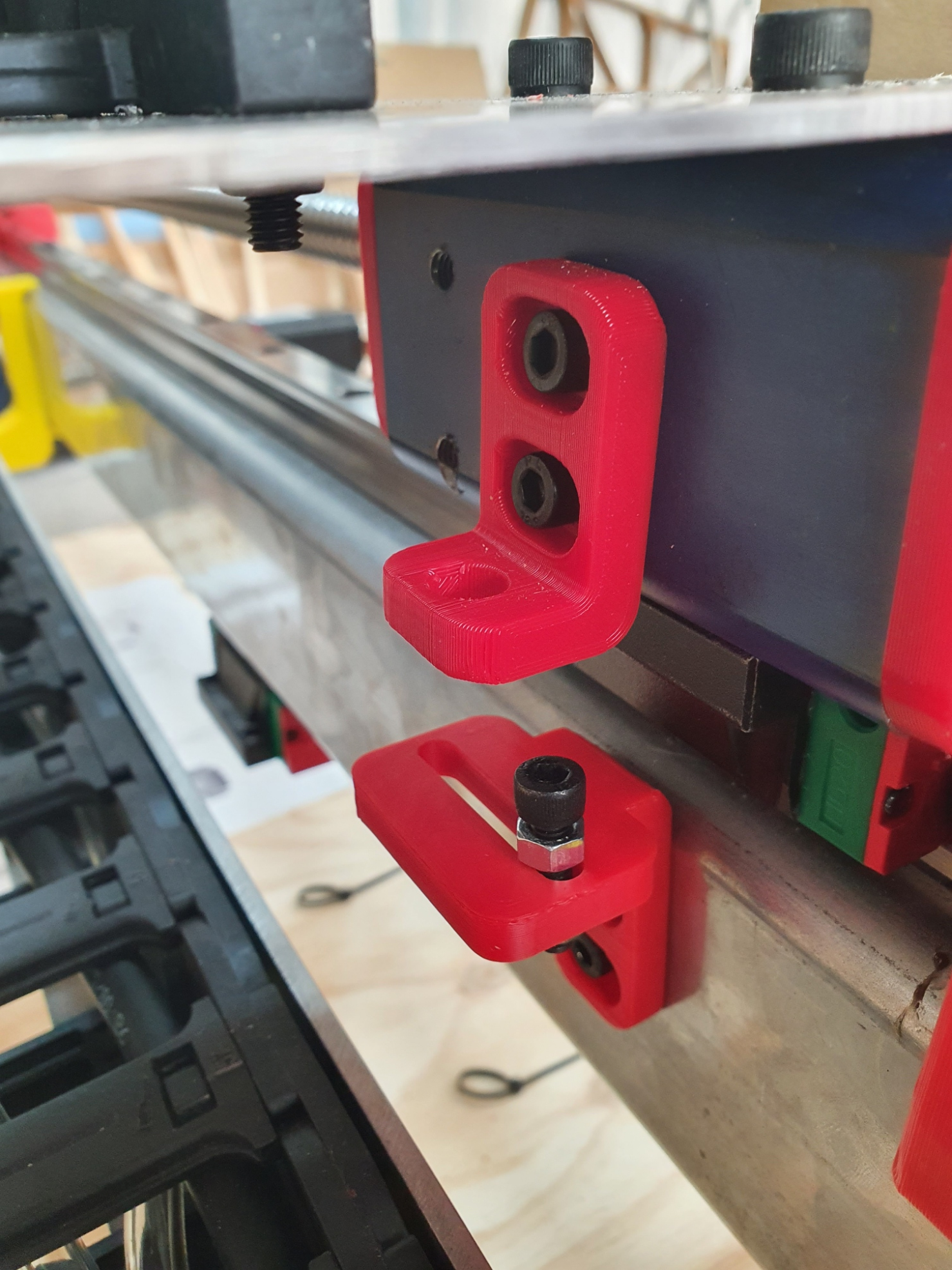
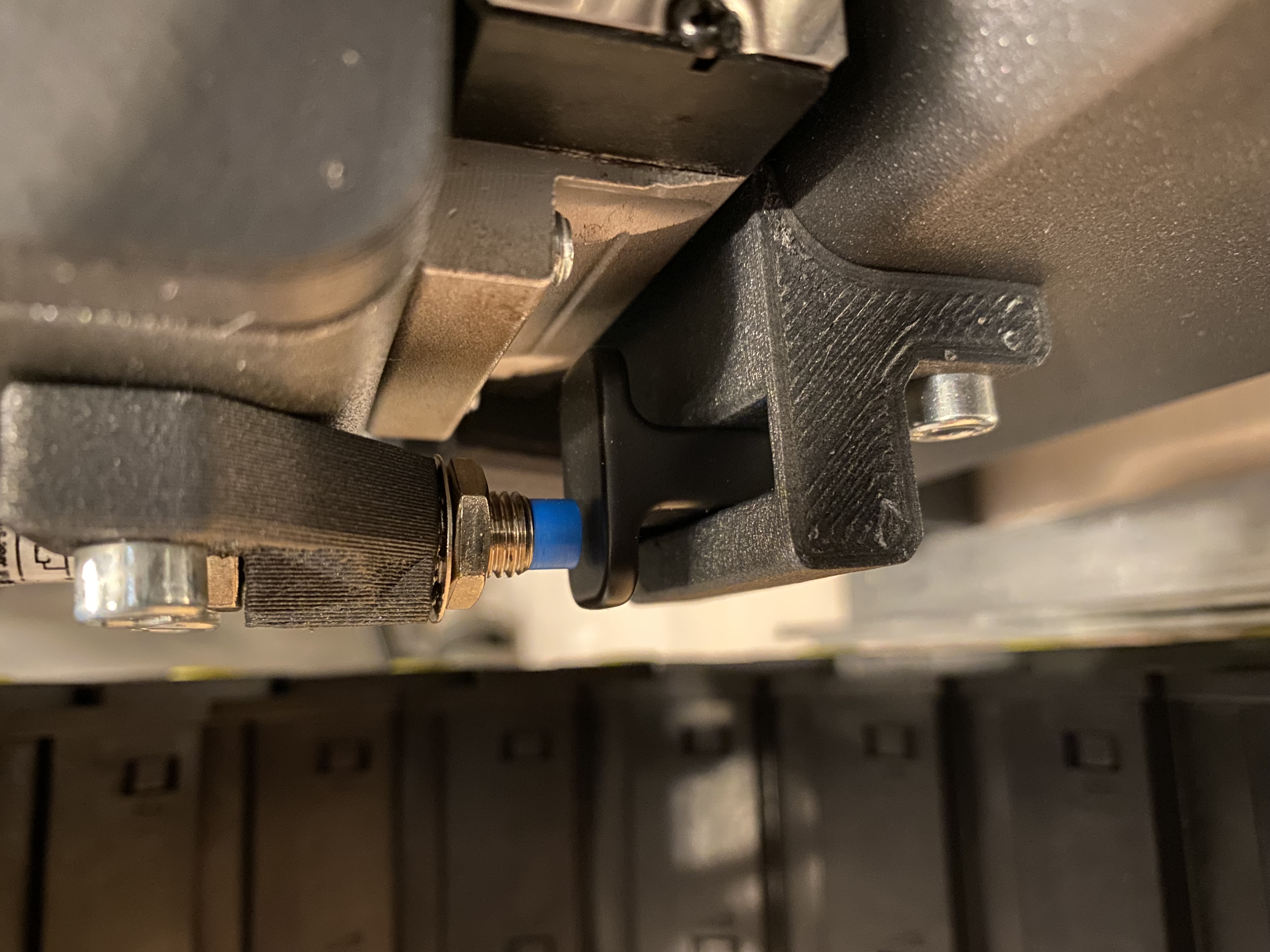
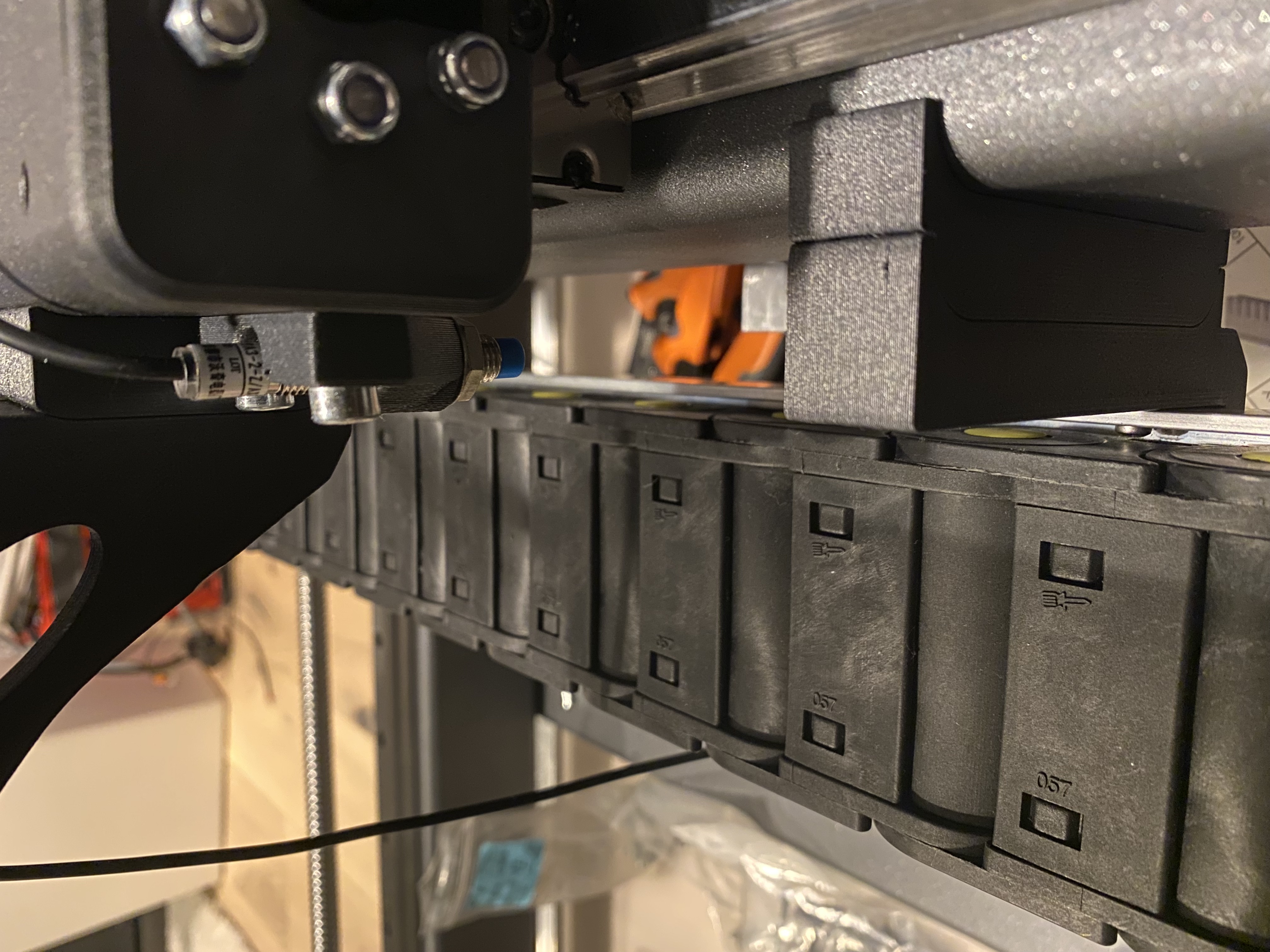
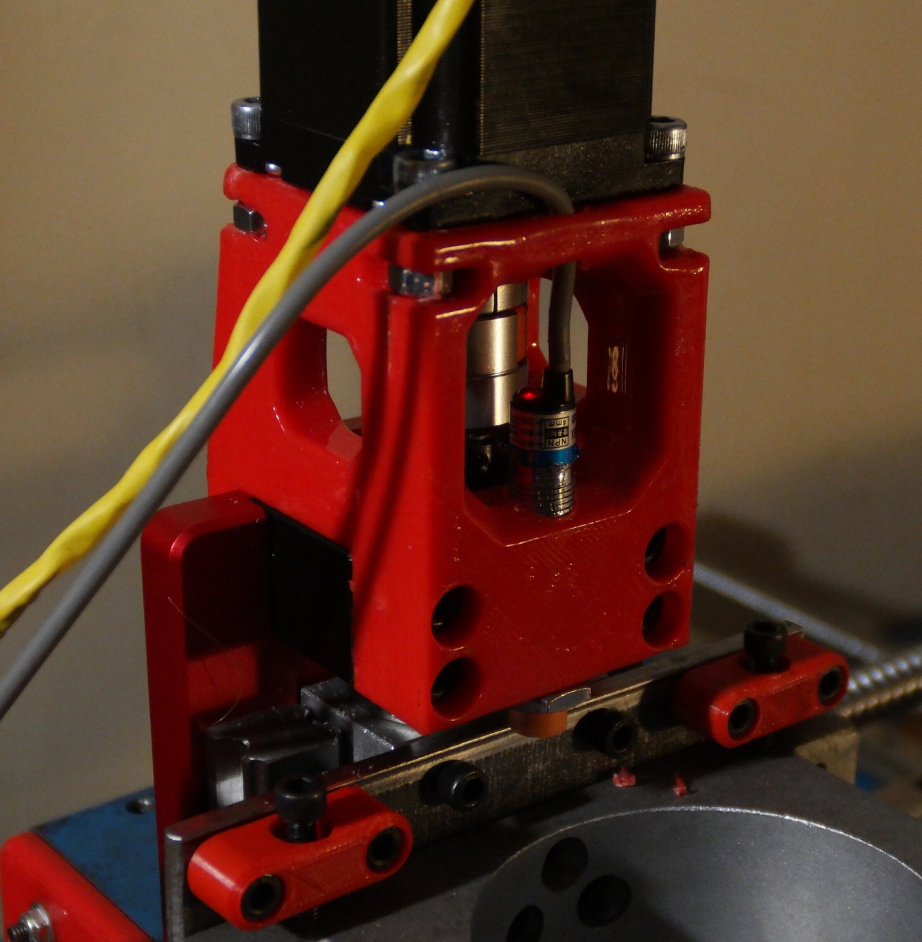
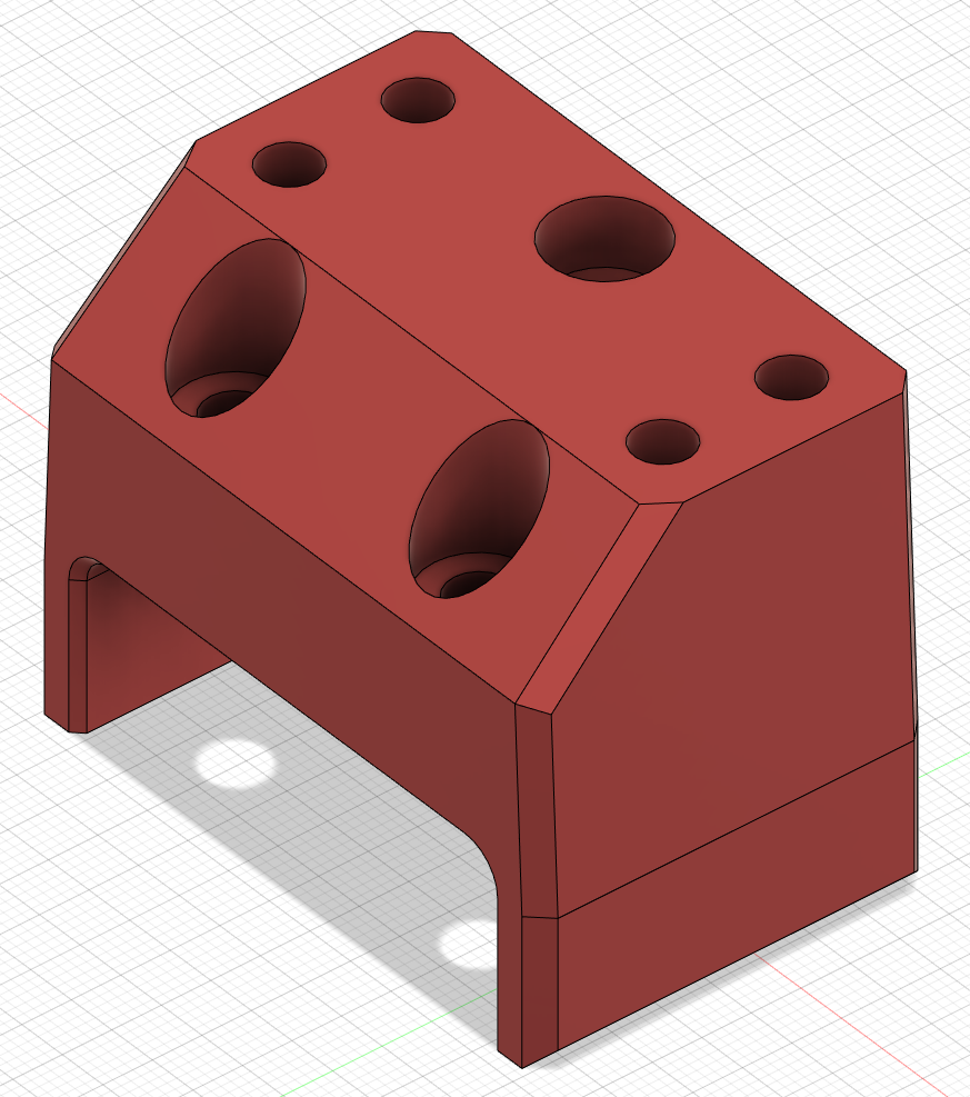
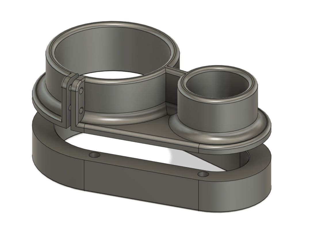
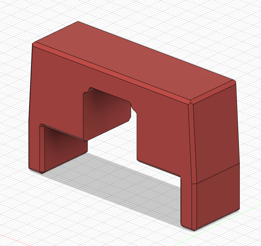
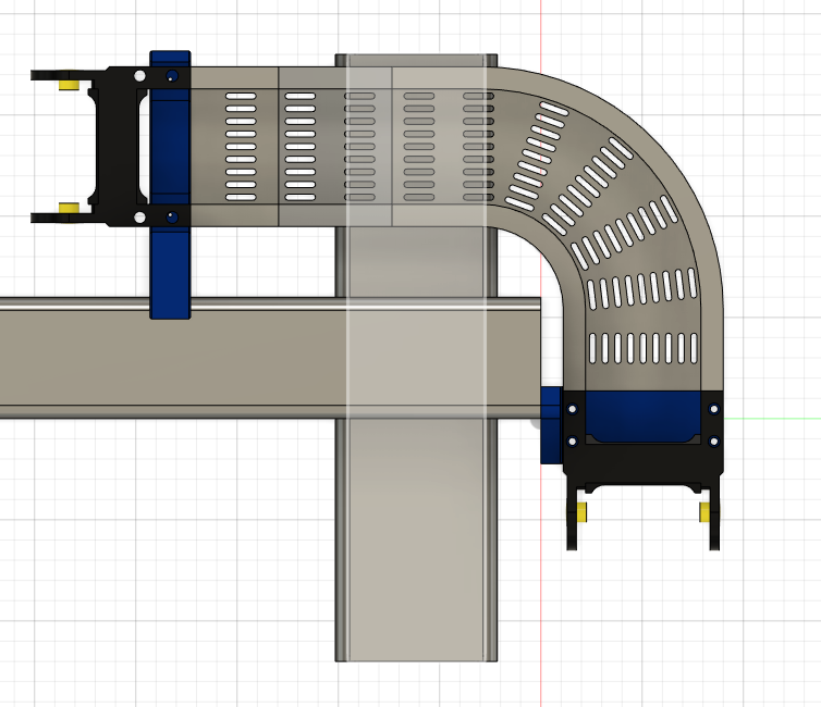
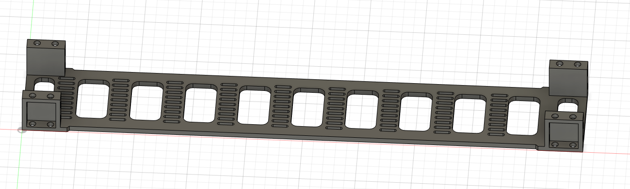
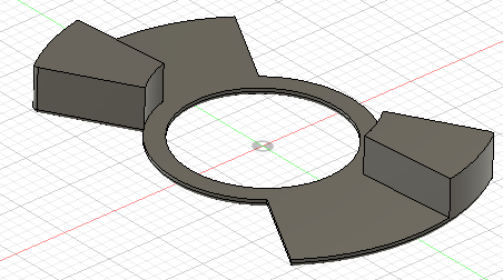
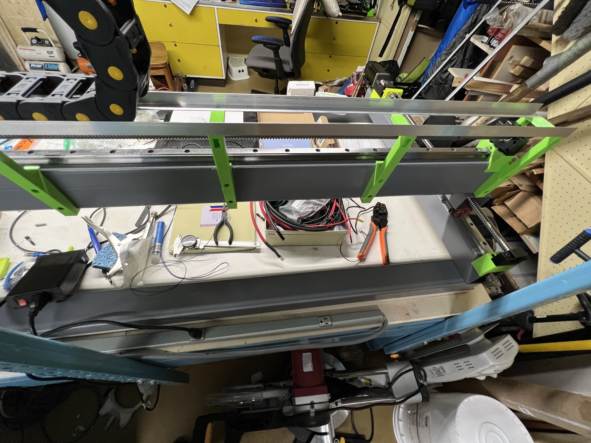
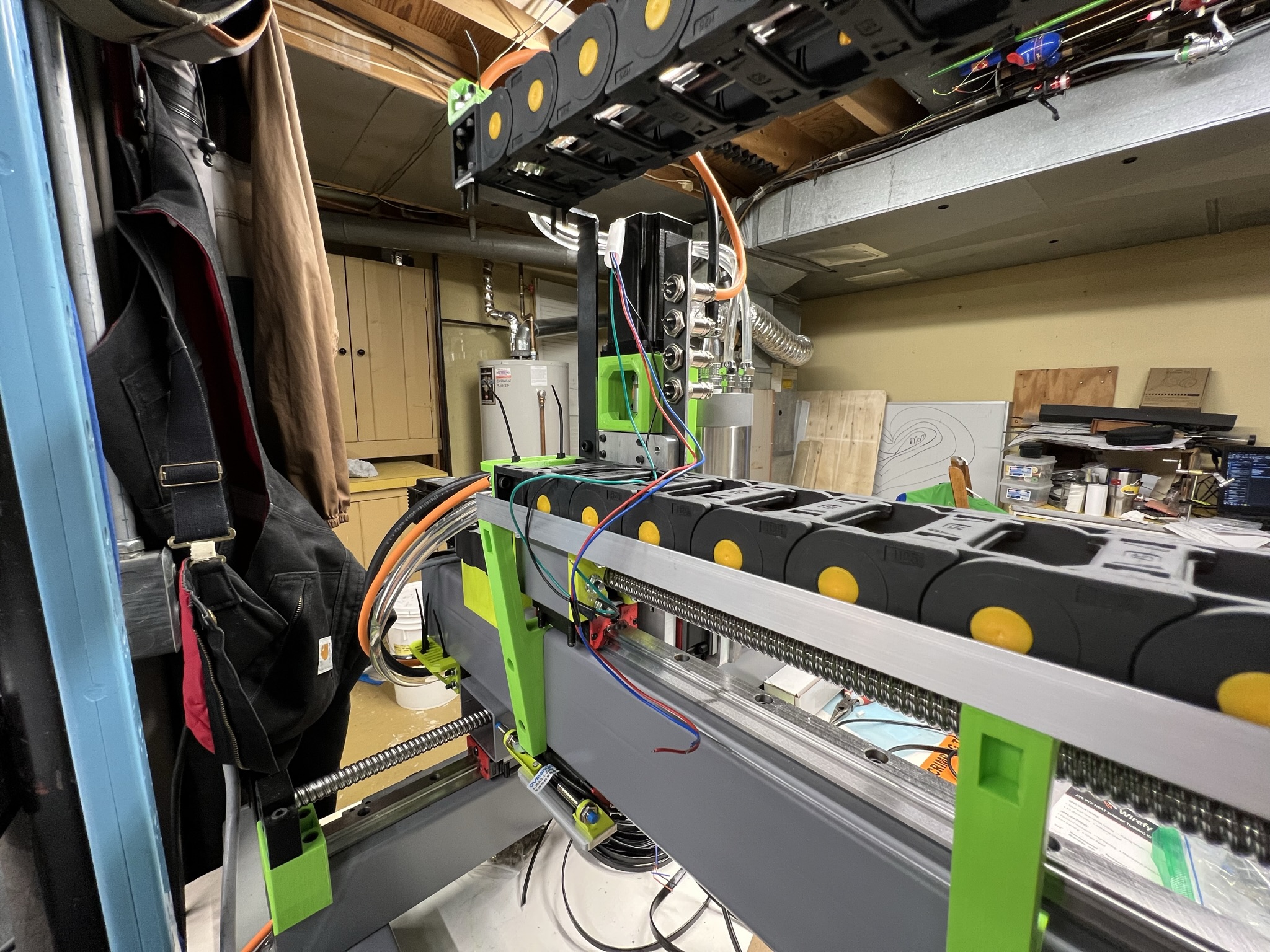
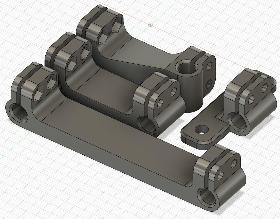
¶ Gantry Plate Mounted X Max & Min Inductive sensor mounts
(by @ThegaLantean)
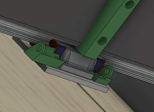
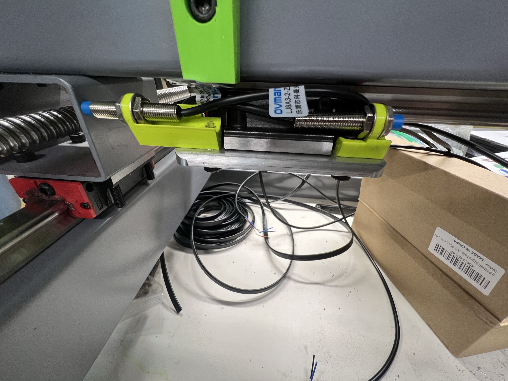
I designed these to mount to the inductive sensors to the aluminum angle of right behind the linear rail carriage. This keeps them out of the way and doesn't increase the foot print of the machine. I'm not sure if there is room for 12mm sensors or not. Note that running the wiring from the sensors to the cable chain is an interesting exercise to keep it away from moving pieces. Also not to leave space around the linear rail block to allow tramming adjustment.
¶ Enclosures
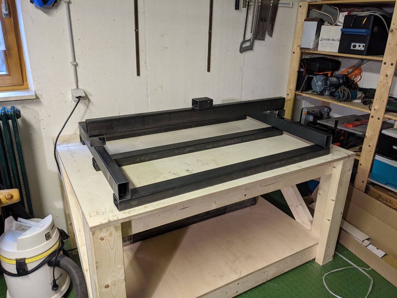
¶ Simple Worktable
(by Waldgichtel)
This is a simple Worktable which is parametric in size and the wood beam size available.
Or download via googledrive:
https://drive.google.com/file/d/1jSTs51MUj3V09PHLSrJo_7yQmY_n6nbh/view?usp=sharing
¶ PrintNC Enclosure / Worktable
(by @lauka)
Design for a full workspace for the PrintNC and its control devices and peripherals.
ThegaLantean asked in the discord how much size is needed beyond the frame dimensions for an enclosure and VanGC supplied the following information
Two inches on front, back, and one side, six inches on whichever side you plan to place your Y drag chain. That's the bare minimum and assumes the insides of the walls are at those point
¶ Dust Shoes
¶ Z-independent Dust Shoe for Z2.1
(by Tayas)
https://www.thingiverse.com/thing:4682475
https://www.youtube.com/watch?v=Cq3LlhZMwkM
NOTE: as stated in the title, this design will not work for the current narrow Z axis.
¶ Parametric Dust Shoe
(by @Logan BC 🇨🇦)
Adjustable spindle diameter, hose diameter, distance between them, and size of magnets. I'm considering a second type that just clips to the outside and can lift up when going over obstacles.
For current version please join discord here https://discord.com/invite/RxzPna6 and check the Fileshare group.
¶ Dust Shoe
(by @nka (♂ [PNC#5] - QC/🇨🇦))
https://a360.co/2OG8Nae (view link only)
¶ Dust Shoe
(by @lauka)
¶ Dust Shoe
by (hoges)
¶ Collet Fan
(by @Logan BC 🇨🇦)
A low-tech budget chip clearing method. Enclosure highly recommended. This will really throw chips around.
Modified(by Banchad) for ER11 Collets:
https://drive.google.com/file/d/1H2G1rzU_KkhUDpgXO1WTSpkVV3U4OpZL/view?ts=603d0e2a
¶ Assembly Tools
¶ Frame Squaring Tool
(by @Tayas)
¶ Motor Bracket Drill Guide
(by @irrenhaus 🇩🇪? or @jay_s_uk?)
https://a360.co/39K2QCV (later) https://a360.co/2X8tqAB (earlier) (view links only)
¶ Spindle Drill Guide
(by @KillSwitch404)
A spindle drill guide that includes the tramming holes (TAPPED!) as well as the through-holes.
¶ Linear Rail Center Guide
(by @Logan BC 🇨🇦)
Print two or three to help align your X and Y1 rails with the steel when tightening the bolts.
¶ Steel Radius Measuring Tools
Use to determine the radius of your steel tubing for setting base parameters before printing parts for your PrintNC.
¶ Rail Transfer punch holder
(by Laurens D)
A simple transfer tool holder that you can put into the hole of your rails. You can modify the settings to make it fit your transfer punch. With this you are guaranteed to hit the center spot.
The current settings work for my printer and filament (ABS), but you may need to modify to suit.
https://drive.google.com/file/d/1ubJ_FDkK3KVaV-q4f0C1qg7P5Mm77i5F/view?usp=sharing
Ps: Sorry for the bad parameter naming
¶ Ball screw carriage holder 1610 (for the short side)
(by Laurens D)
This is a simple holder for your carriage to avoid losing balls while mounting/removing the carriage. It' s specifically made for the short side of the ball screw. You can simply put the holder over the short smooth side of the ball screw, this will make it so that after the threading your cart will go directly on the holder.
https://drive.google.com/file/d/1BCdaaQoKTJgi23RU5XroTg0uwyylad43/view?usp=sharing
Ps: Sorry for the bad parameter naming
¶ Miscellaneous
¶ Cisco PSU housing
(by @rpatterson)
https://drive.google.com/drive/folders/17396ZA1hVRTjxXP3y9dxV0rbhAid5L_Z?usp=sharing
Print one housing and two plastic pins. To install on the PSU, remove the two stainless screws (large heads) that hold the mating connector on the PSU. Use M4x0.7mm (35mm long) machine screws or bolts to hold everything in place, reusing the mounting points of the two original screws.
See the https://wiki.printnc.info/en/electronics/power-supplies page for more details (pinouts, etc).
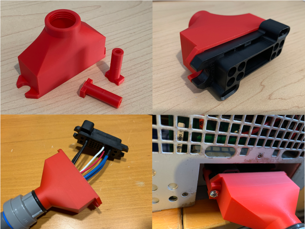
A simple side input port version:
https://drive.google.com/file/d/1bm__x3G-_rOWhsISSlz1oWQyXkkpROXI/view?usp=sharing
The f3d files are lost, unfortunately. Hope this can help someone. The credits goes to the one who originally created this: (by @rpatterson) as seen at the top. Mod by @LaurensD
¶ Collet Rack
A simple collet rack.
¶ Collet Wrenches
(by @Alex BC)
There is a param call SIZE, just replace with SIZE_SMALL or SIZE_LARGE to get the different sizes. Also added a tolerance param to give a little wiggle room for easier engagement.
/mod images/collet_wrench_v2.f3d
¶ Parametric square pipe plug
Caps for the ends of your steel struts, if you aren't using them for wire routing or epoxy granite.
https://www.thingiverse.com/thing:1229682
¶ 3d Object Digitizing Probe
While not PrintNC specific, this is possible and has been done by other hobbyists (and professionals). A brief discussion about it can be found here:
https://forum.sienci.com/t/using-a-probe-to-digitize-an-object/1019
¶ Metal Holding Vise
@logan: I'm using a 5" jaw vice.
I think it was this one: https://www.busybeetools.com/products/5in-precision-machine-vise-craftex-cx.html
¶ Parametric 35mm din rail mounting bracket
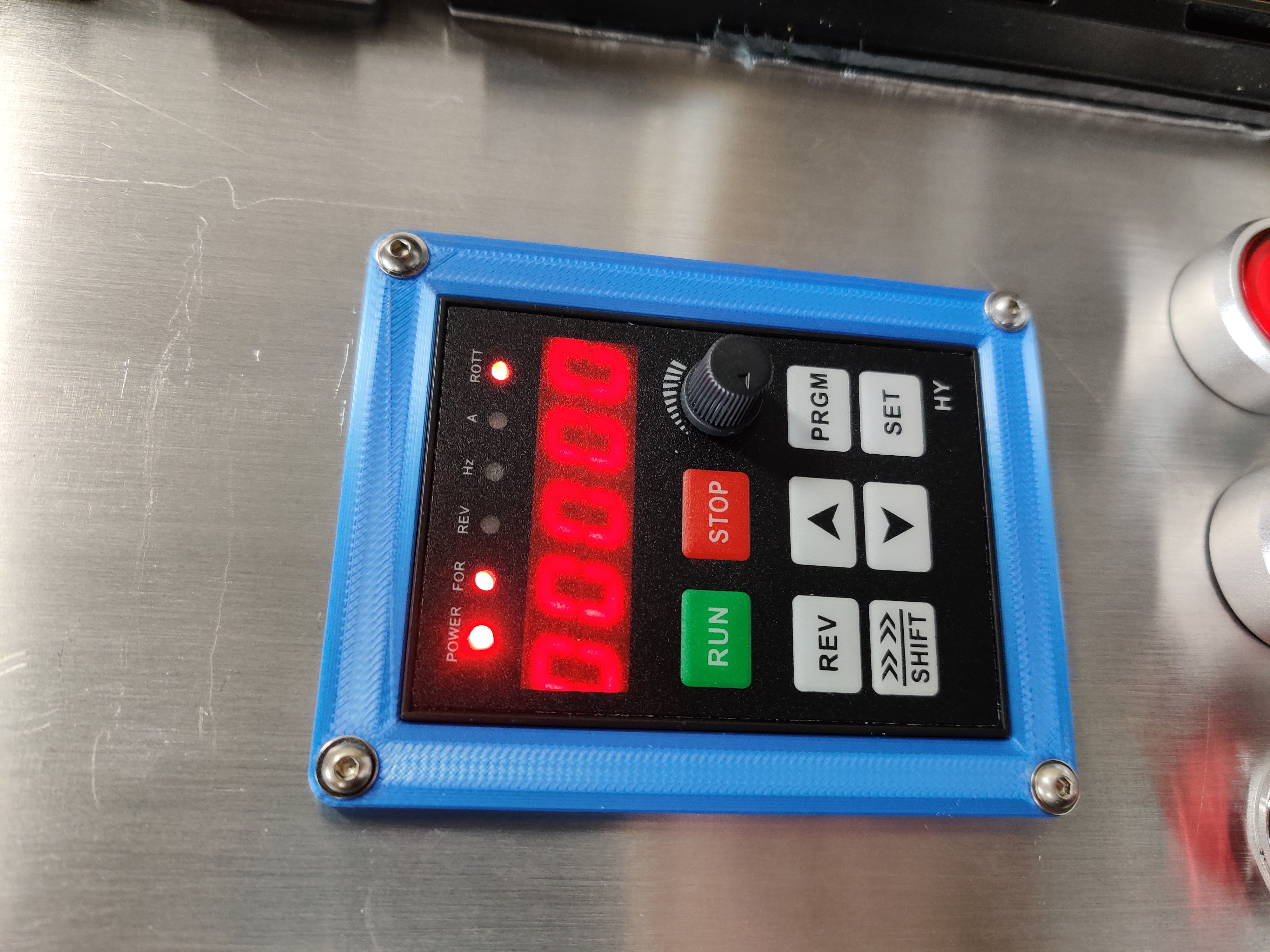
¶ VFD Faceplate
Originally designed by Logan
¶ Cable Chain
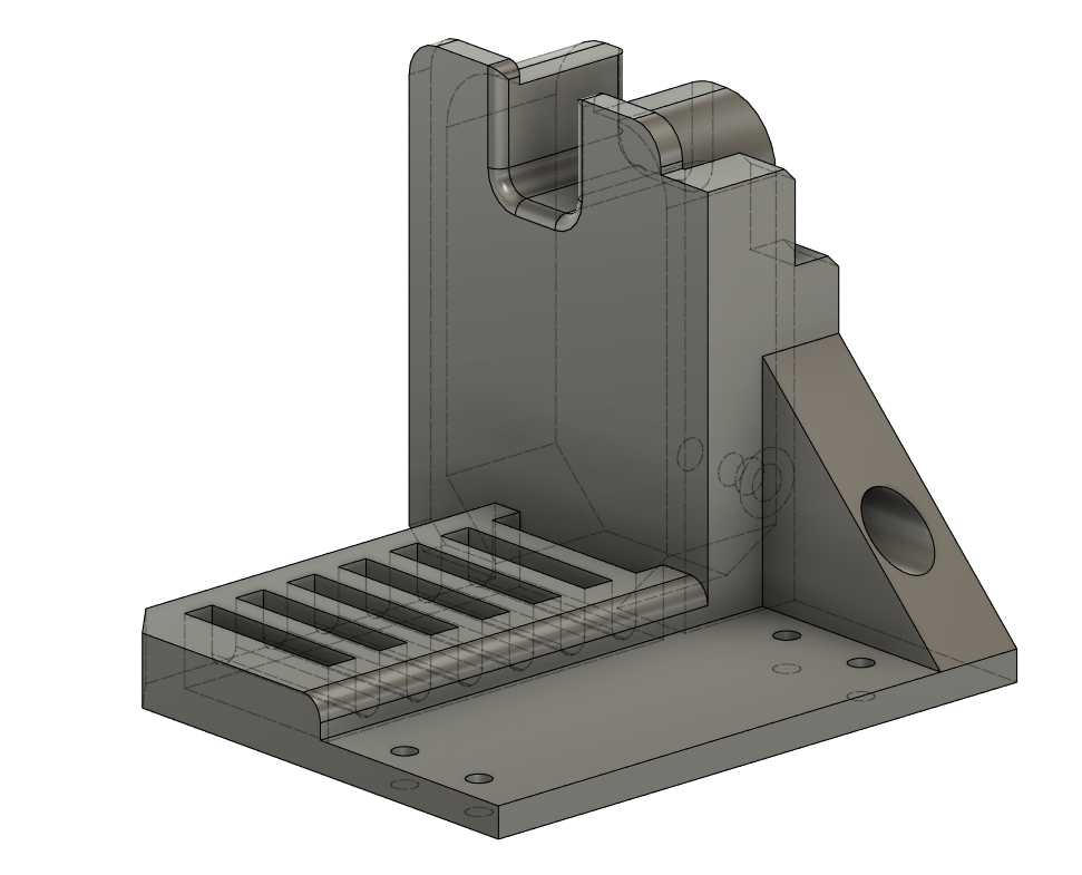
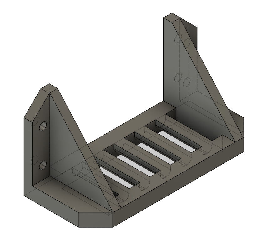
¶ Printable Cable Chain Brackets
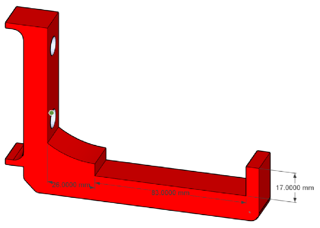
(by kjordan - the L-bracket updated by rtfm)
The original L-brackets by kotlikm positioned the cable chain too close to the probe brackets. I am using the ones by deime (1st one in this list). I simply:
(1) extended the spacing by 26mm to provide sufficient clearance
(2) increased the cradle length to 83mm - in order to accommodate both the chain and an (optional) 3mm aluminium angle to support the chain)
(3) and increased the outside lip slightly (to 17mm) to ensure the cable chain sits snugly.
NB This thing is not parametric, so the face which bolts to the steel tube may or may not fit perfectly. This fit is non-critical (i.e. it is mainly cosmetic) since all the load is carried by the two bolts.
I printed this with 35% infill (Gyroid - Cura) and it seems perfectly strong enough. If worried, you might wish to increase the infill slightly.
You can find this on Thingiverse (https://www.thingiverse.com/thing:5558713)
X Axis Gantry Mount (kotlikm)
Other Cable chain holders (done by many in Solidworks, re-done in Fusion 360 by "Flukester QC"; consider these “beta” as they're still being tested/improved):
/cable_chain_support_x_bottom_single_v3_v1.f3d
/cable_chain_support_x_top_single_v1.f3d
For the Y chain (on the side of the machine), we have two options to attach at the end of the gantry tube. One option requires the gantry to be about 85mm longer and brings the chain above or below the gantry tube. The other option does not require the gantry to be longer and brings the Y chain at pretty much the same height as the X chain. The bottom part of the Y chain is meant to go flat on the table, besides the frame. If your table doesn’t extend far enough, you can use L-shaped brackets for the bottom part of the Y chain but they’ll need some adjustments to align properly with the top part.
/cable_chain_y_mount_gantry_end_v4_v1.f3d
¶ Strain relief
(by Stefan H)
¶ Cablechain Bridge
(by @clehn8ok)
connects the Y-cable chain to the X-Gantry cable chain:
Here is the “parametric”-ish cable chain bridge:/printnc_paramentric_bridge_v3.f3d
here are all the files i used, and some more pictures:/printnc_cablebridge.zip
Cablechain Extension
(by @clehn8ok)
extends the cablechain to whatever lenght you build it,
- input the overall length you need to extend
- than the number of holes ( length/50)-1 -→ so when you need 270mm extension = number of holes=270/50-1 = 4 So in quanity holes you put 4
- than you need to re-extrude the first sketch, since it changed the length and the number of holes, the rest should generate correctly
/printnc_parametric_cablechainextension_v1.f3d
¶ Cable Chain Plug & Linear Rail Plug (for extra fancy-ness)
¶ Strain relief for cable chain
(by @Luddi)
¶ Cable chain insert for changing chain radius
(by @koenich, updated by @Deime)
This part can be inserted in the cable chain to change its radius to increase the service life of the cables. The insides of the drag chain sides are numbered 1 and 2. These inserts are numbered accordingly . It prints ok at 0.2mm layer height with a 0.4mm nozzle, but make sure that the material lets go of the buildplate easily, as the base of the print is fragile. The file is fully parametric, you should only need to change the desired radius and printing tolerance. The file is tested with a 150mm desired radius. In the end this print resulted in a 155mm radius drag chain.
¶ Cable Chain supports for holding the chain over the X Gantry
(by @ThegaLantean)
These parts can be used with 2 lengths of ¾ x ¾ x 1/8 thick aluminum angle to support the cable chain over the gantry. Designed for 12mm M6 bolts to hold to the gantry and #8x½ flat head screws & nuts to attach the aluminum angle. Designed for 2"x4" gantry tubing. Design is not fully parametric, but I'm throwing it up here in case anyone else wants to use it. For the end that attaches to the Z-plate, I simply bent a piece of steel into an “L” shape and bolted it to my Z-Plate.
¶ Tramming and Calibration
¶ Assorted tools for attaching 8mm rod and dial indicator to the spindle or clamp bolts for tramming
¶ Tramming Measure Clamp
(by @lauka)
A clamp for temporarily attaching a dial gauge to the spindle.
See the Tramming section for more info on when and how to tram.
¶ Ball Nut Housing Fixture Clamp
(by @Ivan Stokic)
The fixture clamp is a +0.2mm snug fit and uses 4 M6 bolts on the top for the actual 3d printed fixture and 2 M4 bolts for the nut housing to prevent it from moving up while milling.
For if you want to move from the plastic version to the alu. version without having a proper vise.
Nut housing type: DSG12H for RM1204
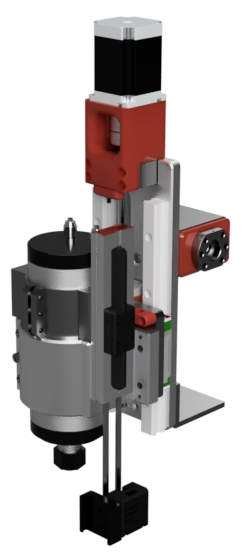
¶ Laser attachment
(by @Marv)
Pneumatic lowering of a laser module.