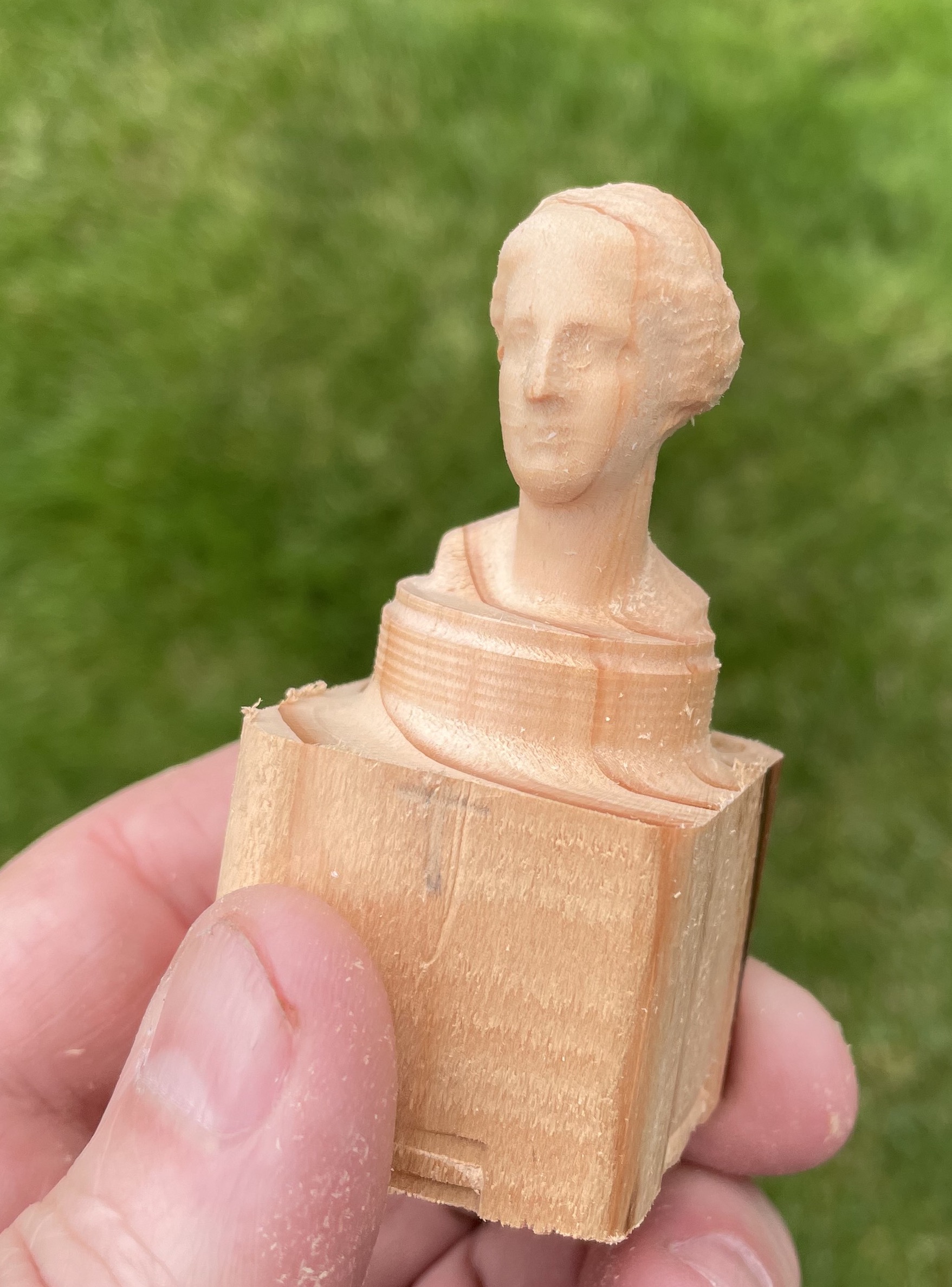
¶ 4th Axis machining
The fourth axis generally revolves around the X axis, and is commonly referred to as the “A” axis.
¶ Use cases:
- Want precision for multi-sided milling. If you mill one side, rotate 90, then mill another side. That is referred to as “indexed machining” or “3+1” in the case of a 4th axis, or “3+2” with indexing 4th and 5th axes. You're really doing 3 axis milling, rotate the piece, then do one or more 3 axis milling operations. I assumed at the beginning of this journey that this would be the main use case for me. As I'm working with a 4th axis more, this may not be my main use case.
- Want to have fewer setups on multi-sided milling
- Examples of some items that are good candidates for 4th axis machining:
- a bust or a statue
- intricate table legs (if you have long enough area between the tailstock and vise)
- model boat: specifically the geometry of the hull
- model car: contours plus having the ability to rotate to each side, even under the car
- airplane and/or wings
- baseball or cricket bat
- chess pieces
¶ What is needed:
- software to do the CAM:
- The free version of Fusion 360 does not allow for continuous 4th axis operations. I think the paid/subscription version of Fusion 360 will allow for 3+1 machining. To get continuous 4th axis, you need to purchase the expensive “Machining extension” annual subscription, which is US$1,600/year plus you have to have the annual subscription of $500/year. You can do “indexed machining” aka “3+1” machining with the free version of Fusion 360. (ex: do normal 3 axis milling on one gcode, rotate the part, then do another 3 axis milling)
- DeskProto is a really good alternative, but does take a bit of learning to feel comfortable with it. The cost for the hobby, multi-axis edition is 300 euro. CAD is still done in another program (like Fusion 360), but the CAM is done in DeskProto.
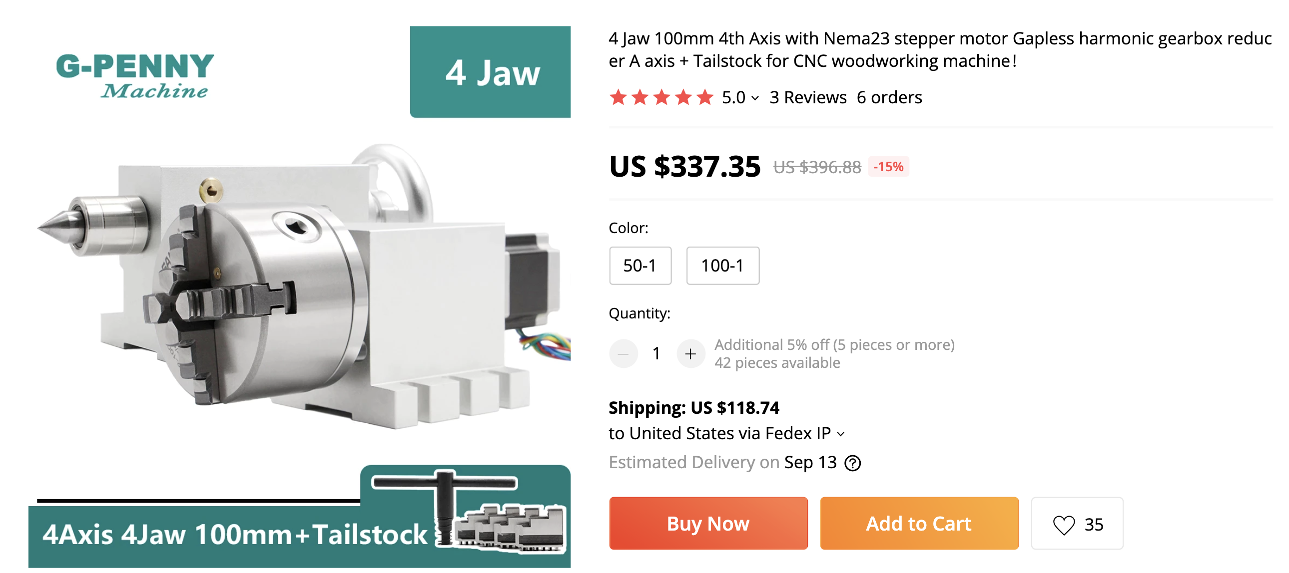
- 4th axis motor/chuck: There are many options. Jaymis purchased this one from GPenny on Aliexpress and selected 50:1 drive ratio. The main types of 4th axis are:
- Harmonic Drive - More expensive. Low backlash and high rigidity, but slower rotation. Best accuracy for indexed machining and better rigidity to machine metals.
- Belt Drive - Less expensive. Higher backlash and lower rigidity, but generally faster rotation. Should work well for wood, but may lack rigidity for heavy cuts in metal.
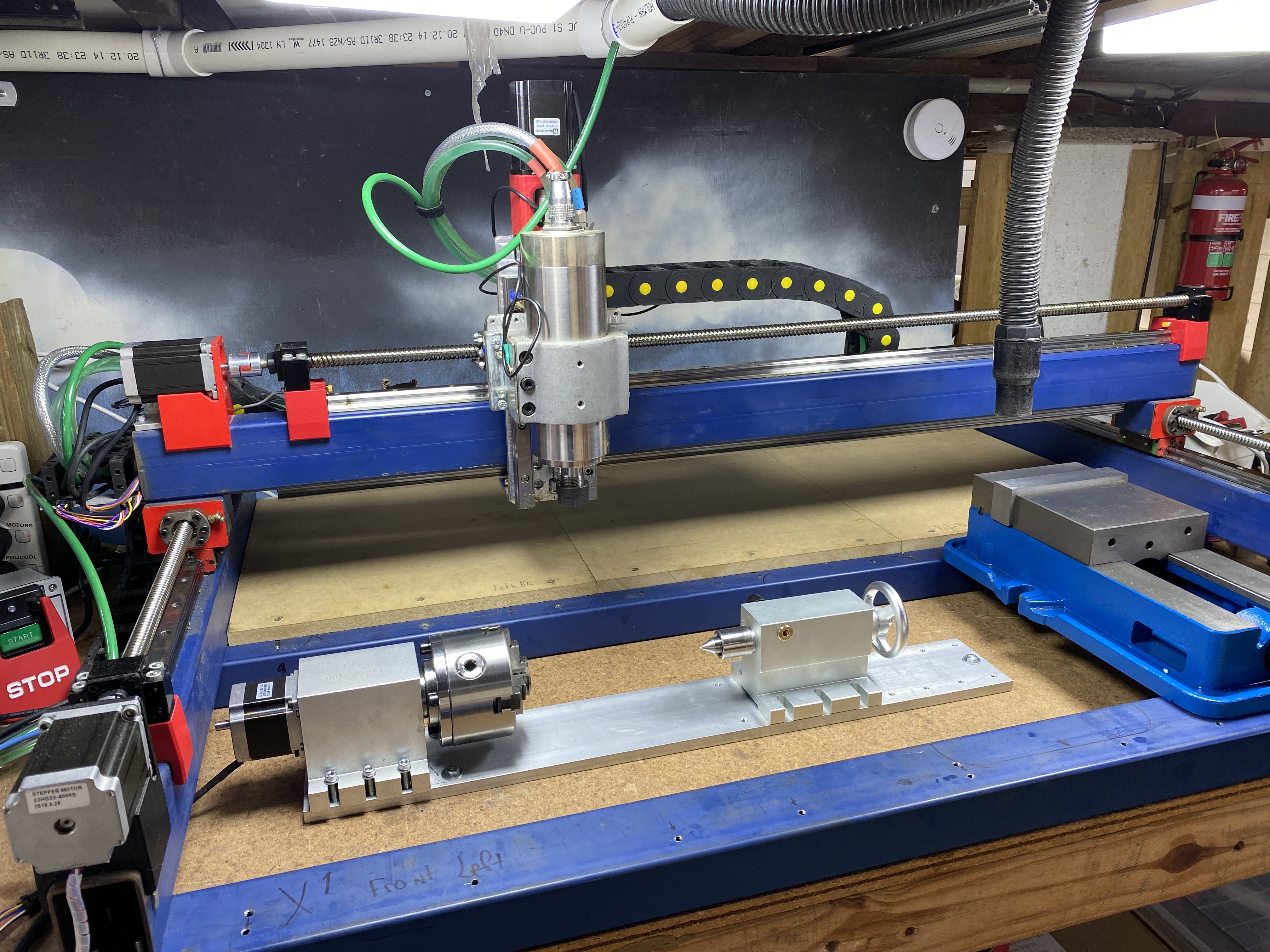
- way to mount the 4th axis motor to the PrintNC
- tailstock (optional): Recommended for parts where stickout from the chuck is more than 2-3x part diameter. Many 4th axis kits will come with a tailstock. It needs to be precisely aligned with the chuck's center of rotation.
- tailstock alignment bar (optional): To align the tailstock with the chuck, you can purchase a precision machined round bar that you mount in the chuck, then use an indicator or 3d probe to ensure the chuck and tailstock are in alignment with each other and the PrintNC frame
- dial indicator or dial test indicator (optional, but highly recommended): Allows you to precisely align the chuck and tailstock to the PrintNC rails and with each other.
- configuration in your controller (LinuxCNC, grblHAL or other)
- another stepper driver
- wiring on your Break out Board (BoB) or Mesa board for another motor
- willingness to experiment, learn something new
¶ Work holding
Chuck:
- Many types are available. Commonly 4th axis kits come with a 4 jaw self-centering chuck, which can be used to hold round or square stock. A more flexible option is a 4 jaw independent chuck, which allows you to hold rectangular and irregularly sized work pieces, and to more precisely dial in alignment. Blondihacks on Youtube has a great primer on 4 jaw chucks.
- There are two different sets of teeth that came with the 4 jaw self-centering chuck: an inner and an outer. They are numbered. Each slot requires the appropriate piece. Make sure that when one “falls out” (by opening the jaws too much), they need to be inserted at the correct turn of the chuck. The easiest way to verify, is to completely close the vise with nothing in the vise. All teeth should meet in the middle.
- You can put cylindrical stock in the middle of the vise and slide it into the housing of the vise. This ensure a nice good clamping surface.
¶ Tips:
- Try to have uniform sized stock (at least at the left edge) so the vise will have some really good surface to clamp to. Be sure to select cylindrical stock in DeskProto if using cylindrical stock. For example, I accidentally checked cylindrical but I was using rectangular stock. The “corners” were doing a much deeper depth of cut than expected, due to the geometry.
- If work piece is long, strongly consider using a tail stock
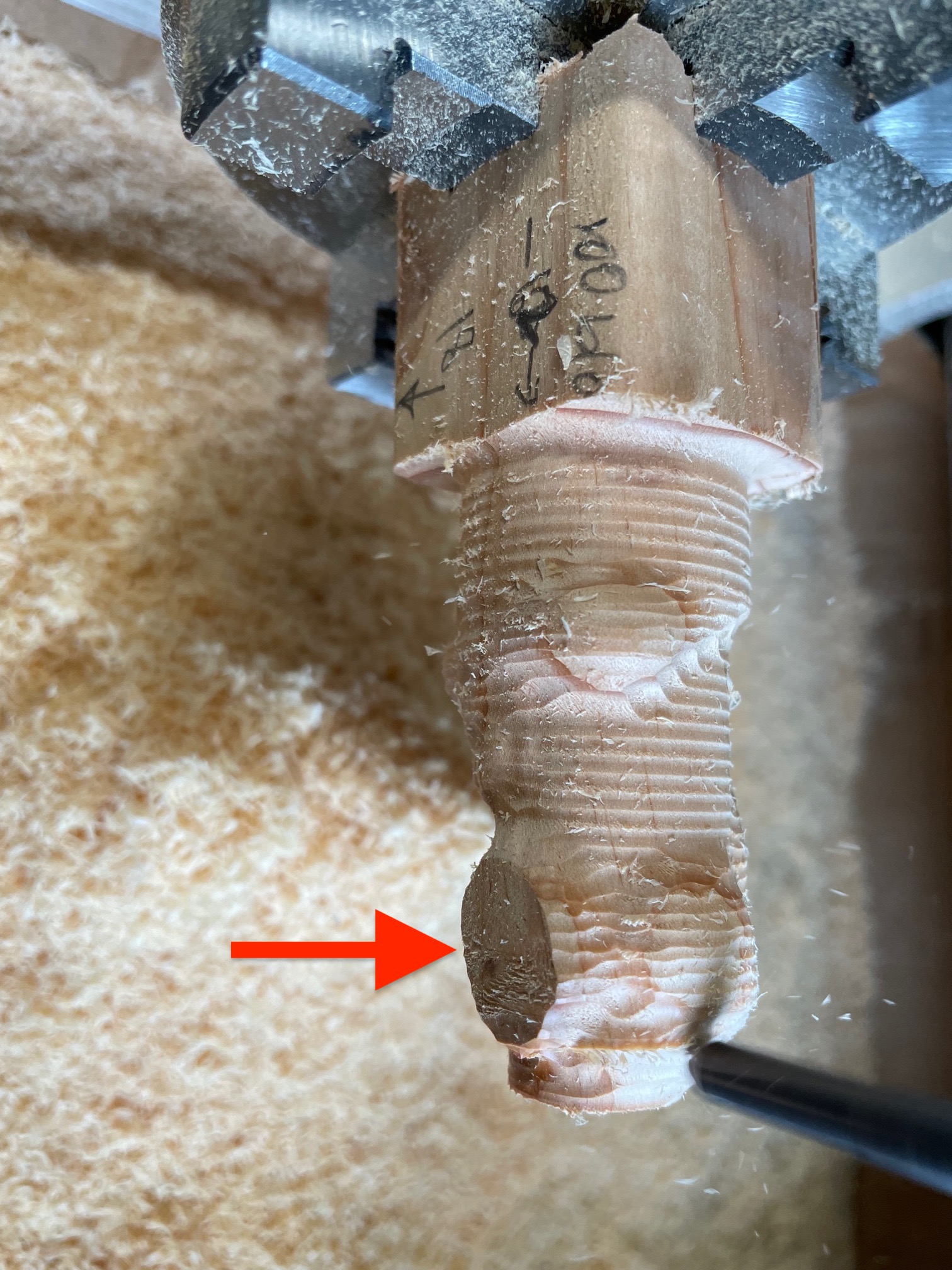
- Try to give yourself some extra stock to cut on the “Z” because if you put in your piece a bit off center, then you may not make sufficient cuts into the material (see picture below). In the picture, the wood is about 36mm wide and the work piece was not put into the vise exactly square (hard to do), there was no roughing done on that part of the piece. There is a 1mm “skin” on this run so it still might get fixed in the finishing pass.
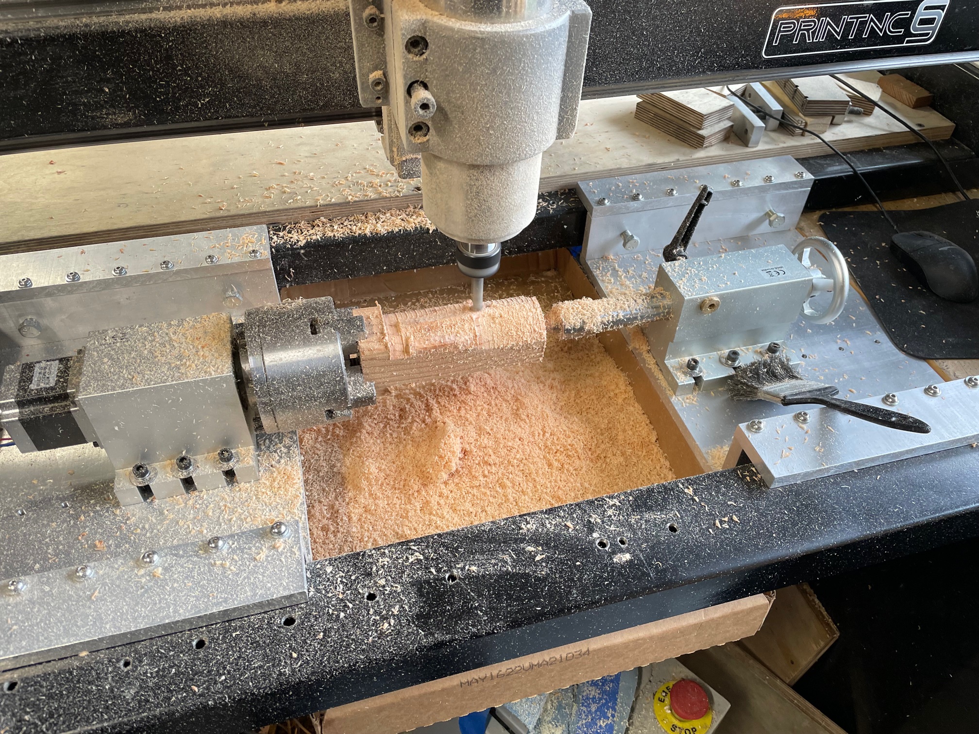
- Cut down the stock to a reasonable size before trying to mill it (otherwise you are just going to take a really long time, make lots of noise and tons of chips)
- Consider having supports on the left and right of the work piece so you do not crash the spindle on the vise nor tailstock
- Consider starting with simple designs such as a small, cylinder so you can verify the calibration
- Longer bits are better if you have a large work piece:
- cuts more material
- avoids crashing spindle into edges
- Do not need to “home” the “A” axis per se. Just be sure to “touch off” the “A” when you have everything setup. I try to keep the material level in the vise, rotate it 90 then 180 and verify it still looks level. Then I go back and touch off the “A” axis.
- The “Y” axis does not move at all during operations.So, you will want to touch off the “Y” in the middle of the stock (if that is where you set the origin in CAD)
- Jogging the the “A” axis:
- In GRBL-based software it might be the “+” and “-” on the number pad
- In LinuxCNC, it is the “[” and “]” keys. Be sure to HOME the machine before hitting those keys, as they will move the Z axis, and possibly running your Z into your Z sensor.
¶ Pictures:
