¶ Squaring
There are a few different techniques for squaring:
¶ 4 Point Squaring - Recommended for PrintNC V4.
Details here https://wiki.printnc.info/en/v4/squaring
¶ 3-4-5 squaring
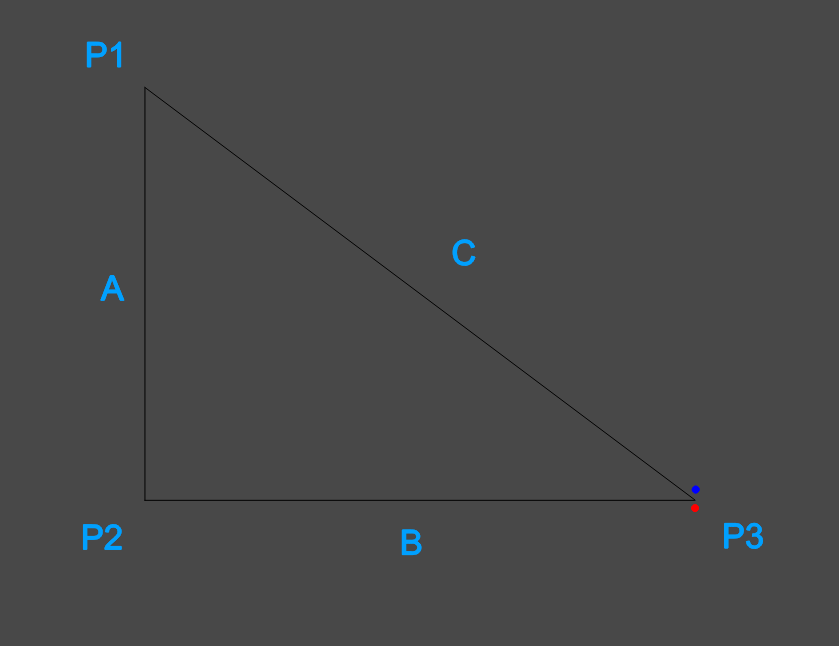
This method uses a simple 3-4-5 triangle to check for machine square. The general theory will be to choose a number for your “unit” that will give you the biggest triangle without exceeding any of your machine dimensions. For example, if your machine is 4 feet by 2 feet, the best triangle you could use would be 24"x32"x40" (8" being one “unit” in this case).
- Put a fine pointed bit in your spindle. Flat PCB engraving bits are not a good choice as the point is not general on center for them. Other types of engraving bits will work fine.
- Cut 3 pieces of tape, and mark an X somewhere near the center on them. Put these to the side.
- Move your spindle to somewhere close to a corner of your machine, bring the spindle down near the surface, and put one piece of tape on the spoilboard so that the X is in line with the tip of the bit. This is now point 1. Zeroing your X and Y axes at this point will make the remaining steps far easier.
- Move your machine 3 units along your shorter axis, and repeat the marking process.This is point 2.
- From point 2, move your machine 4 units along your longer axis and repeat the marking process again. This is point 3.
- Now, measure from point 1 to point 2 (this is measurement A), point 2 to point 3 (this is measurement B), and point 1 to point 3 (this is measurement C).
- Verify that measurements A and B are exactly equal to the expected values. Using the example of 24"x32"x40" above, this would mean A=24" and B = 32". This is confirming that your machines steps per unit values are correct.
- Confirm that your C measurement matches what is expected (40" in the example). If it does not, adjust your Y axis end stops and repeat the test. When adjusting, assuming your triangle is laid out as in the figure below, if your 3rd point is below where it was expected to land (red dot), then you will need to adjust your right Y axis limit toward the back of your machine. If it is above (blue dot), do the opposite. Once you have confirmed that measurements A and B are correct, you no longer need to run steps 3 - 5, you can simple tell your machine to move directly from point 1 to point 3 using an MDI command like
G0 X24 Y32(assuming that you are working in a work offset where 0,0 is your point 1).
¶ 3-pin squaring
- WARNING - This process requires disconnecting and re-connecting stepper drivers. Always turn the stepper drive power supply off before plugging or unplugging
- Get 3 x 4mm Drill Bits (or similar)
- Drill 3 holes through a piece of wood and into the wasteboard in a large triangle that is pointing to the left side of the machine. Note the XY position of the far left hole
- Use 2 of the drill bits as locating pins, put them in the waste board then flip the wood along the X axis and place the wood back down onto the locating pins
- Return the machine to the noted XY position and move the Z axis down to the stock top
- If the gantry is not square then the drill bit won't line up with the hole
- Disable the Y2 (right) stepper by unplugging it, then jog the left side of the gantry until the drill bit can be moved down into the hole with perfect alignment
- Note the difference in machine position to the original position. The difference between these positions is twice your gantry misalignment Divide the result by 2, enter that number as your Y1 offset
¶ Q - For the 3 pin squaring process, do you "drill" the holes with the router? I'm unsure how to make sense of the process because I'm thinking if I drill the 2 holes on the right (on which the piece of wood is flipped) it'll result in issues but I'm unsure.
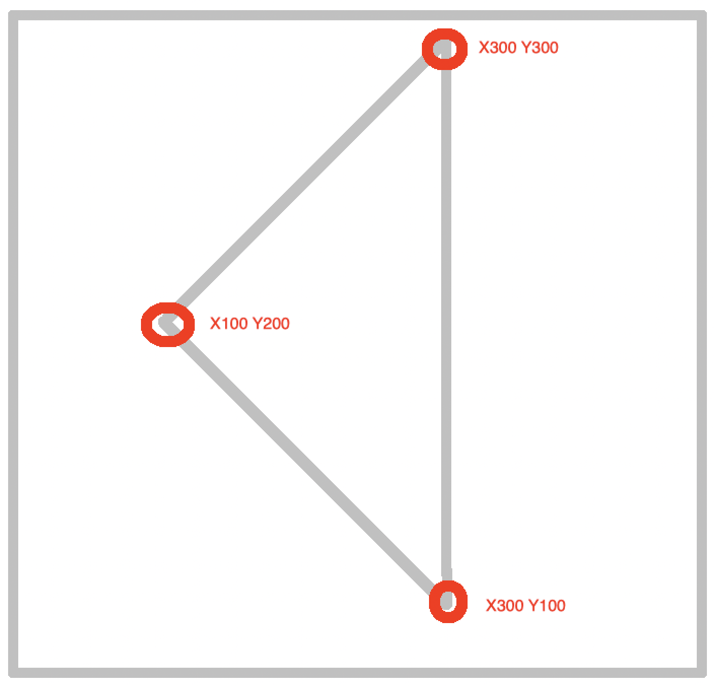
hoges: Drill with the router through the piece of wood to be flipped and into the wasteboard - remove the wood and place 2 drill bits into the holes you created. Flip the wood then try to plunge (slowly) into the 3rd hole, unless your machine is already perfectly square the 3rd hole won't be aligned. For example (These aren't the required coordinates, just an illustration):
¶ Z Axis Squaring and Spindle Tramming
You need to square your z-axis as well as tram your spindle. For example, your spindle can be perfect relative to your stock, but if your z-axis is at an angle and you make a hole, your spindle may be straight down but it will make an oval as there is some sideways motion to your plunge.
¶ Tools and Jigs
It is recommended that you have a dial gauge for this step, though the “paper feeler gauge” can work for most people. Tuning farther will be needed if you work with aluminum which is less forgiving for surface finishes or when working with wider bits which will also accentuate the “shingling” effect of an out of tram router. All instructions are written assuming a dial gauge. You don't have to spend a lot on a dial gauge as precision (i.e. repeatability) is more important than accuracy in our case.
For the Z axis a machinist square is valuable, a speed square can work but it is recommended that you repeat in both directions if said square is not at a perfect 90 deg.
There is benefit to using jigs designed by the community like:
Tramming Measure Clamp (by @lauka) or one of the Dial Indicator Mounts (by @Logan BC 🇨🇦) . If you have a dial test indicator you might also like the CNC Spindle Tramming Dial Test Indicator Holder (@MichelTheriault).
Also having lead screws, or shims can be valuable for less “fiddling” when you work on your CNC.
¶ Reference Surface
The first step in tramming is having a good reference surface. It is recommended that you start with a piece of float glass or something equally flat (many people take the glass right off their 3d printer!). Attach your dial gauge somewhere on your Z carriage and move your Z down until it just touches the glass.
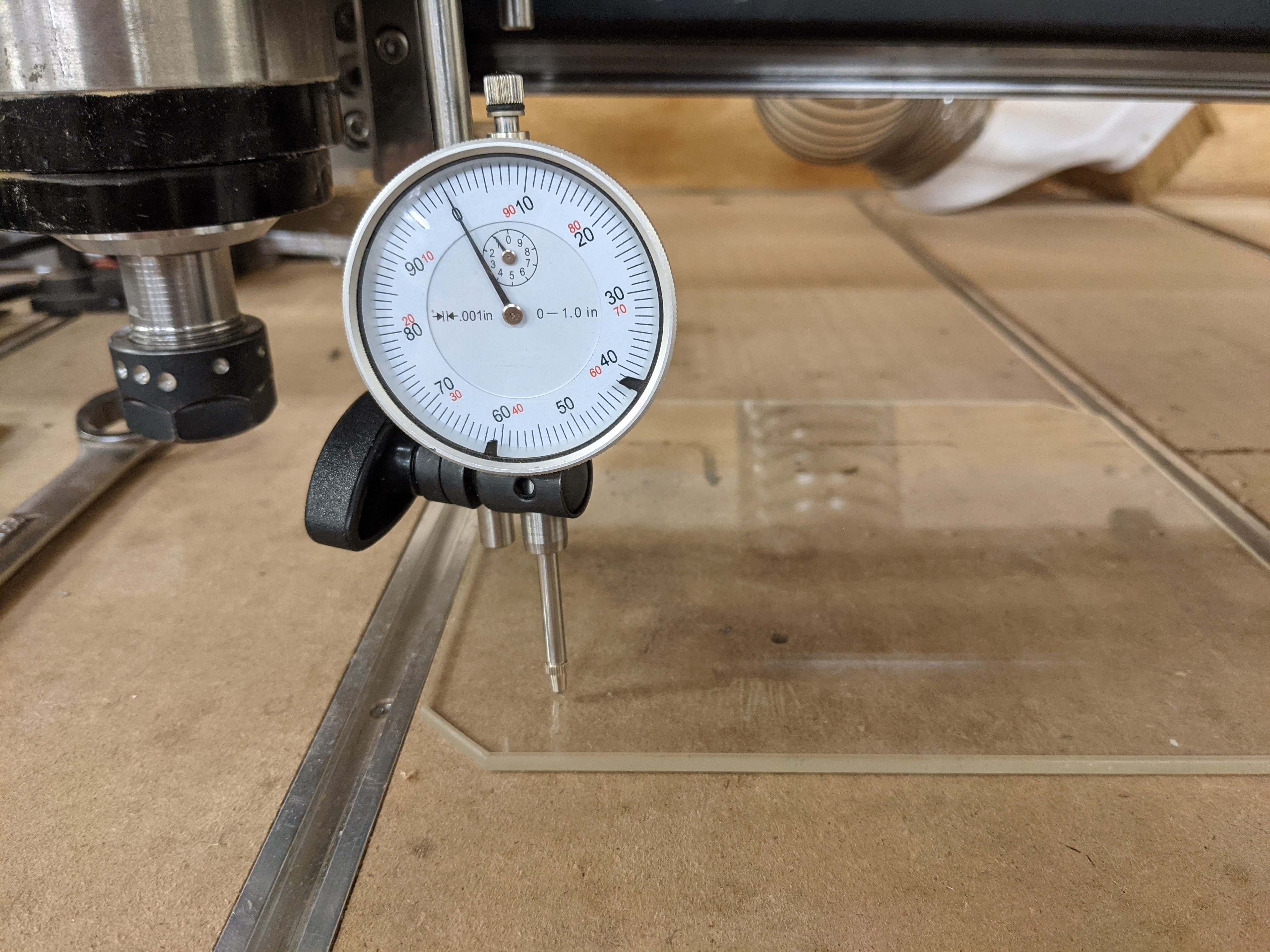
Move your CNC across the glass and add shims where needed to level the glass.
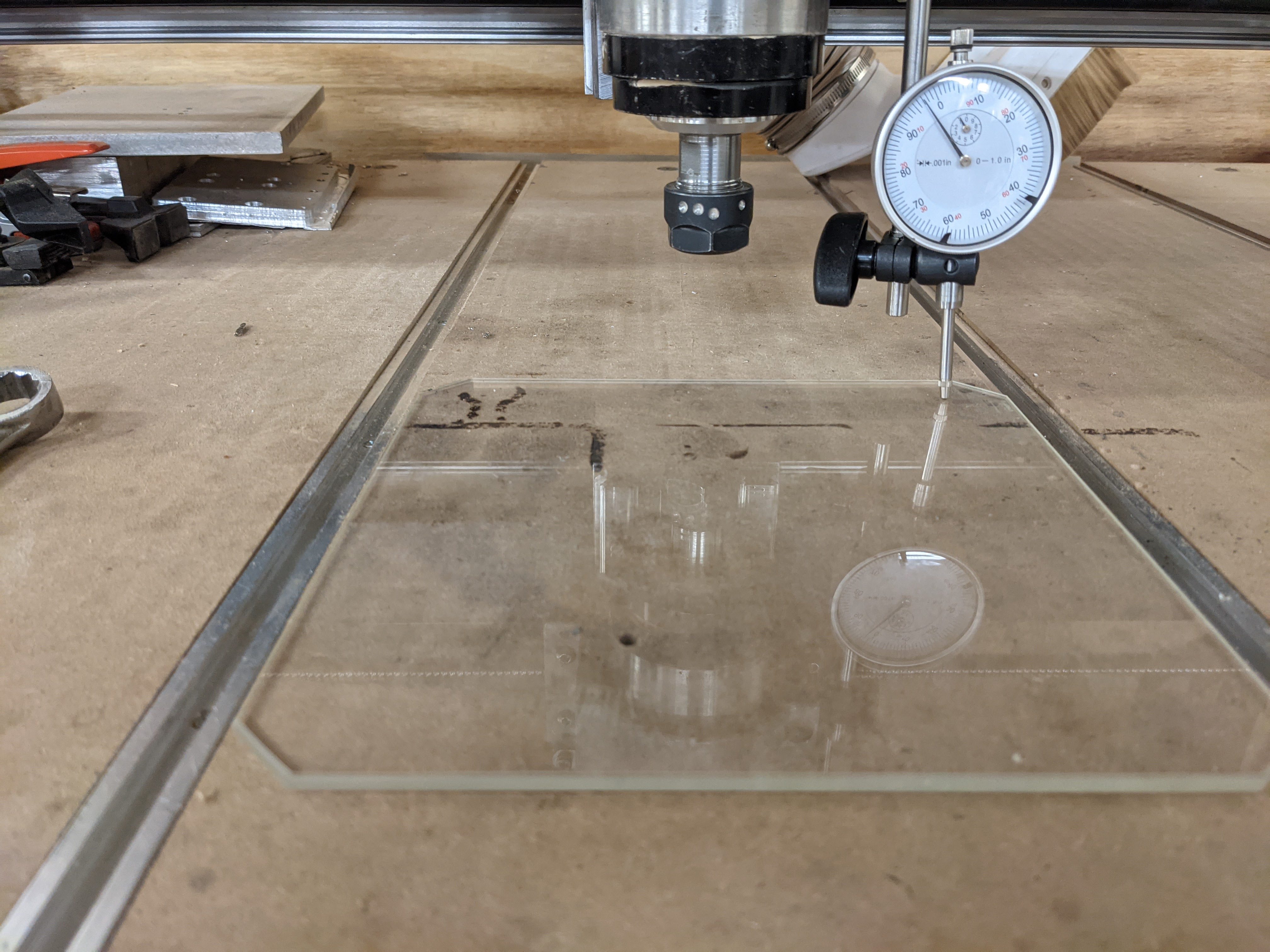
In the above photo you can see I need to raise the back right portion of the glass by about .003inches or .07mm. I use a leaf taken from my feeler gauge to level my glass. This is much like leveling your 3d printer. You may have to go back and forth a few times to get your glass plate perfectly level.
¶ Z-Axis Squaring
The first part is starting with squaring the Z-axis to the Y-axis or the “nod” the Z axis (imagine nodding your head up and down if you were the spindle).
Move your dial gauge so it is as parallel as possible to your plate and your Y axis. Again we are looking for precision here, not accuracy. Put your square on your reference surface and move it so it just touches your dial gauge, if you don't have any friction on your surface it may be necessary to put a small heavy object behind your square (seen in following pictures).
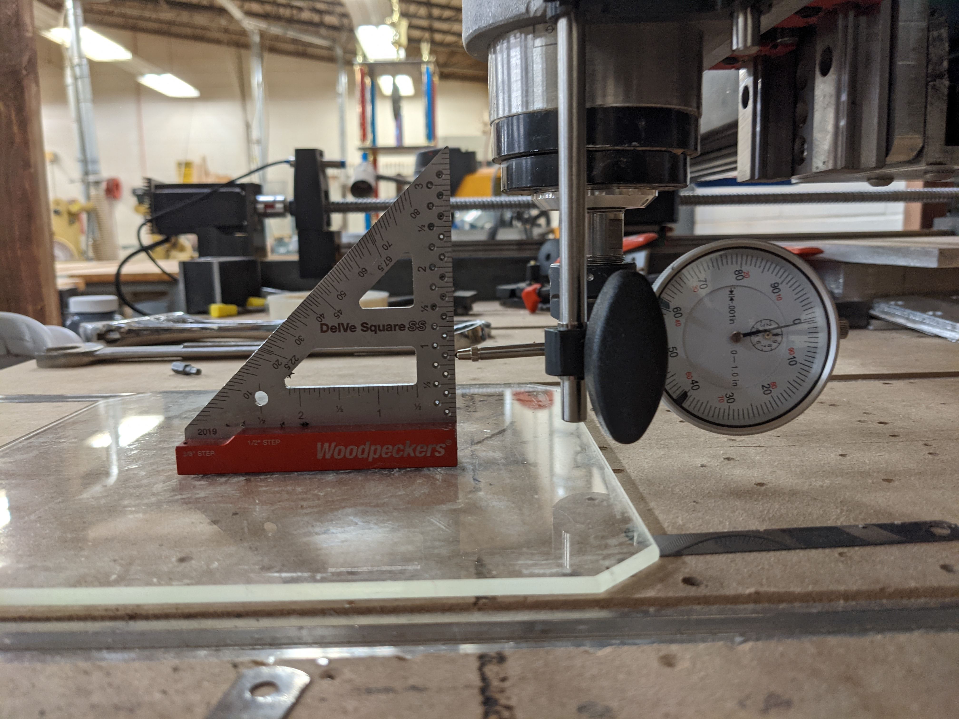
Once your square and dial gauge are in place and you've noted your initial measurement slowly jog your z axis up the side of your square and watch how the dial gauge changes.
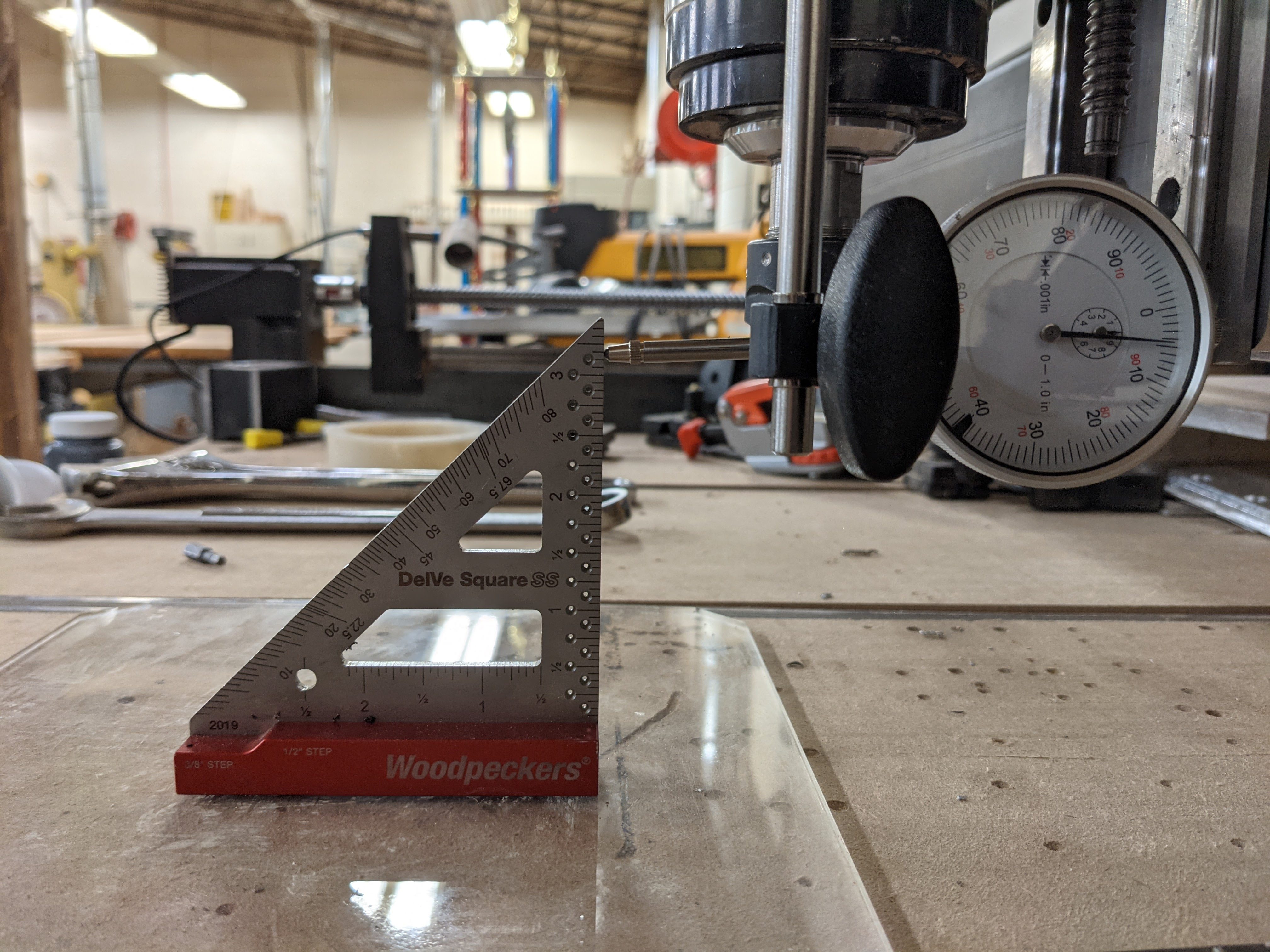
As you can see in my photos, the value increases from about 0.5 thou to 4.8 thou as I bring the Z axis up. From how we've set this up in the above pictures, this means the top of the Z axis is too close to the front of the machine, so we need to adjust this.
When you need to loosen some bolts in the next steps, it usually means to still leave them hand-tight, so everything stays in position until it is pushed by a controlled force.
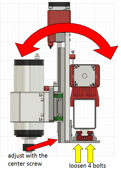
To adjust the rotation around the X-axis, you need to loosen the 4 bolts connecting the alu angle to the lower X-carriage. Now you can use the lower center screw in the alu plate to push the plate away from the lower X-carriage. It's best to start with pushing the angle to the back and then moving it forward with the screw. When the Z-axis moves parallel to the square, tighten the screws again.
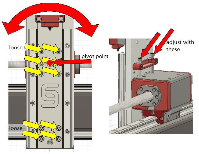
To adjust the rotation of the Z-axis around Y you need to loosen the 4 screws clamping the alu plate to the upper X-roller and the 4 bolts clamping the alu plate to the lower alu angle. The alu plate will not fall because it sits on the bolt head in the center of the upper roller which acts as a pivot point. Use the bolts in the tram bar on the back side of the alu plate to push the alu plate in a rotation around the pivot point. Again move the Z-axis up and down until it moves parallel to the square. Tighten all screws again.
¶ Spindle Squaring
Whenever you tram the Z-axis, you will need to tram the spindle as well.
Now you need the tram bar mentioned above, which clamps into the spindle collet and holds a dial gauge. Position the spindle centered above the glass, so the dial gauge can be rotated in a circle around the spindle axis, contacting the class plate. The spindle is trammed correctly when the dial gauge shows the same value in the front and back as well as left and right.
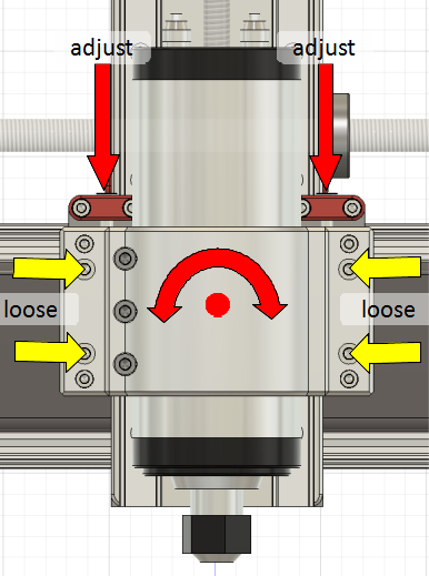
To adjust the spindle tramming around the Y-axis, loosen the 4 bolts connecting the spindle clamp with the tram plate. Now you can use the adjustment screws on the shoulder of the tram plate to rotate the spindle clamp on the tram plate. The spindle clamp rotates around the bolt head in the center of the tram plate.
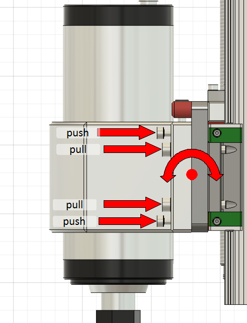
To adjust the spindle tramming around the X-axis, you use the M5 bolts in the spindle clamp to push the clamp away from the tram bar in the upper or lower part and use the M6 bolts to pull it tight.
For a good video watch the following guide by Mark Lindsay CNC
or a video by Tim
https://www.youtube.com/watch?v=A0w6Ddb0ViY