This method computes the Y dual axis offset needed to square a gantry. Its primary advantage is that the error multiplier from measurement to offset estimate is around 2x, while referencing a 123 block or similar-sized square can lead to an error multiplier of 10-15x (source). This method is also fast and easy; we need only center-find a hole/pin four times. There is no cutting, measuring, or other precision work.
For a probe with center-finding accuracy of 0.01mm and a standard work area of 900mm x 600mm, we get an expected accuracy of 0.02mm over 900mm, or within 0.0011 degrees of square.
¶ Prerequisites
For the result to be consistent, the parallelism of the upper and lower X-axis rails must have been checked and corrected if necessary, otherwise this test will be incorrect.
¶ Step 1/5
Find a strip of plywood (or a bar of metal) slightly longer than your work area diagonal. Drill or bore a hole at each end, taking care to make the walls vertical and crisp. If you intend to center-find by jogging a tool (e.g. drill bit, dowel pin) into holes, then the hole diameter should match the tool (or be very slightly oversized). You can optionally insert steel dowel pins if you want to use a 3d probe and an external center-finding routine.
Make the holes as far apart as possible while still fitting within the work area (diagonally).
For other ideas on how to make this strip, see discussion here, here, and here.
Tips: Once you've drilled the holes, say 6mm, in the ends of your stud, you can use a broken or worn bit of the same diameter to position the spindle directly over the drilled holes.
¶ Step 2/5
You can skip this step but then you must compensate in Step 5.
Go to ioSender → Settings: GRBL → Y-axis → 171 Y dual axis offset and set the value to zero. Make sure this setting is saved to the controller. To verify, go to the Console tab and enable the Verbose checkbox. Enter $171 into the MDI and see what is printed.
¶ Step 3/5
Home the machine (or only home Y, if you prefer).
Connect to the calculator and prepare to fill out the form fields.
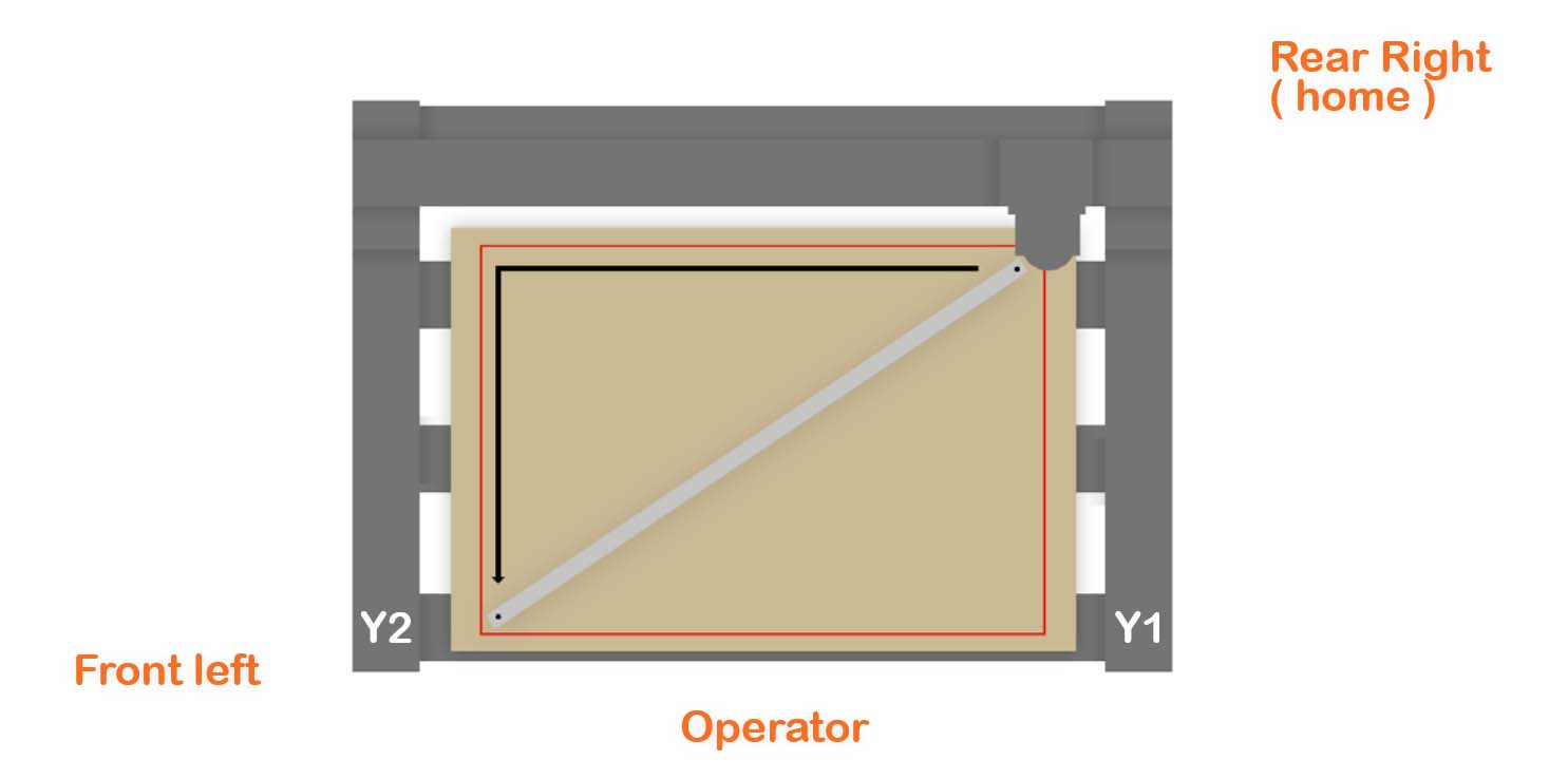
Secure the strip running from front left to rear right (see below). The strip must not move during the measurements!
Find the X and Y coordinates of the front left dowel center and enter them into the calculator.
Find the X and Y coordinates of the rear right dowel center and enter them into the calculator.
You can use a probe, or manually jog-and-aim, or any other method.
¶ Step 4/5
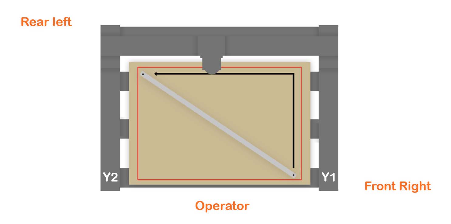
Turn the strip to the opposite diagonal. You don't need to mirror Step 3 exactly.
Secure the strip running from front right to rear left. The strip must not move during the measurements!
Find the X and Y coordinates of the front right dowel center and enter them into the calculator.
Find the X and Y coordinates of the rear left dowel center and enter them into the calculator.
You can use a probe, or manually jog-and-aim, or any other method.
¶ Step 5/5
Measure the distance between your Y ballscrews (from center to center) and enter the data in the calculator, select the options relevant to your machine. The calculator will show the new offset.
Add this calculated offset to the existing offset (which is zero if you performed Step 2) to get the total offset.
Go to ioSender → Settings: GRBL → Y-axis → 171 Y dual axis offset and enter the total offset. If you are limited by a 5-character limit in ioSender, e.g. you cannot enter -0.766, you can either omit the leading zero and enter -.766 or set it directly in the MDI, e.g. $171=-0.766. Make sure this setting is saved to the controller. To verify, go to the Console tab and enable the Verbose checkbox. Enter $171 into the MDI and see what is printed.
Now home the machine (or only home Y, if you prefer). You are done!
To verify squareness, you can repeat Step 3 and Step 4. The calculator will hopefully show your gantry being square or very close to square. If the offset adjustment is within +/- 0.05mm, then you are likely close to the limits of this method.
¶ Maths
Let a and b be the X and Y distances between centers from Step 3, and c and d be the X and Y distances between centers from Step 4. Then the Y offset to make the gantry square is below. If Y offset is negative, the right side of the gantry needs to be brought forward.
Y offset = 0.5*(distance between Y ballscrews)*(a2+b2-c2-d2)/(ab+cd)
You can use this formula to see how errors in a, b, c, and d propagate to the Y offset.
¶ Comparison to other methods
Accuracy is a tricky topic and accuracy claims and comparisons rely on simplifying assumptions. I’m no expert, and in particular, I don’t consider whether inaccuracies in XY travel overwhelm the benefit of probing across the entire work area.
- Probe a machinist square. Even if one leg of the square can be perfectly aligned to Y (e.g. by cutting a perfect pocket), the other leg needs to be 700mm long on X to achieve the same expected accuracy.
- Spot drill points at (0,0) and (k,k) and measure their distance using calipers, and compare to k*sqrt(2). Assuming zero manual measurement error and a caliper accuracy of 0.01mm, k needs to be at least 700mm to achieve the same expected accuracy. Large calipers are uncommon.
- Bryan cleverly uses relative caliper measurements as a replacement for large, accurate calipers. This method is arguably the best. However, it requires a caliper extension and careful manual measurement. See this video for details.
- (Meta) Use multiple methods and repetitions to compute an average offset. This should reduce random error and improve accuracy. However, it’s more work, and it’s unclear how much inaccuracy comes from systematic vs. random error.
¶ FAQ
- Q: Do I have to use a probe?
A: No. Discussion right here
- Q: Does this work for non-grblHAL?
A: Step 5 computes the gantry's angle of deviation from square. This measurement is not specific to grblHAL. There are instructions (in the web form calculator) on how to configure grblHAL to compensate, but of course you can use any other method.
- Q: Why doesn't Step 4 need to mirror Step 3?
A: Discussion right here
- Q: Does the $171 axis offset need to be positive or negative?
A: The web form calculator will tell you.
- Q: When manually jogging and "probing", how do I save time and probe twice instead of four times?
A: Discussion right here
- Q: How accurate does the distance between Y ballscrews have to be?
A: Discussion right here
- Q: What are some different ways to make a strip with holes?
A: Discussion right here
And here
And here
- Q: Why is the web form calculator on jsfiddle, which is so ugly?
A: The wiki doesn't support javascript.