¶ IHSV57 Servos
IHSV57 Servo Motors are a Semi (the shaft of the servo is longer than that of the stepper but just fits using a PNCpro Mount, not guaranteed to work on already installed printed parts, on a virgin build testfit the mount to ensure the ballscrew and servo shaft do not intefere) drop in closed loop alternative to the NEMA23 stepper motors on the standard build.
Though they are rated at 0.6Nm this is the constant torque the motor can output. It can be tuned to allow 300% current draw for several seconds making the peak torque value closer to 1.8Nm.
Because of this the machine power supplies should be considered carefully, IE the 180W draw(for 1 servo) can triple to 540W if the current is at 300%.
Banchad has been running his XY1Y2 servo machine for several months on a 36v 600W power supply and has never had a power shortage (yet)
Wiring:
The drivers for these motors are attached to the motor itself so there is no driver required in the control box.
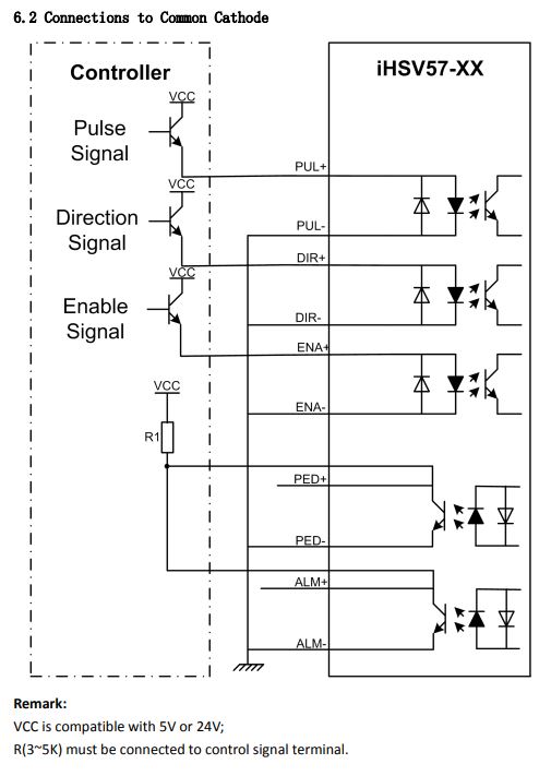
They take a PUL and DIR signal from the controller exactly the same as the stock build stepper drivers.
Only 6 Wires are needed to function at a base level, Pul+, PUL-(GND), DIR+, DIR-(GND),DC+(36V),DC-
You can chain together PUL- and DIR- to reduce the number of wires needed by 1 (It might not be worth it to do this as you can simply run a 6 core wire)
Though not required but highly suggested if the machine has an E-Stop loop the ALM+ can be wired into that to stop machine movement in case of a motor alarming out.
The signal wiring diagram is as below,
Configuration:
NOTE: Before tuning you need to have installed the servo on the machine. They need a load for the tune to work correctly!
These motors are tuneable via a Serial Port cable(RS232). Using a Serial connector that is directly mounted to the motherboard of a computer is recommended as USB to serial (Particularly Prolific driver based adaptors) either do not work correctly or lack the voltage levels to talk to ‘proper’ serial connections. You will need a serial breakout board adaptor like this, https://amzn.to/3l15laZ
The adaptor should be wired to the servo like so, (2)RXD-RX,(3)TXD-TX, (5)GND-GND
It is recommended you buy several serial cables so that you can access the monitoring capability of the tuning software while the machine is moving without risk of the computer being pulled off the desk.
Open Device Manager on the computer you wish to use to tune the servo. Open the Communications port you want to use (IE COM1). Open the Port Settings Tab. Set the following to match,
Bits Per Second: 57600
Data Bits:8
Parity: None
Stop Bits: 1
Flow Control: None
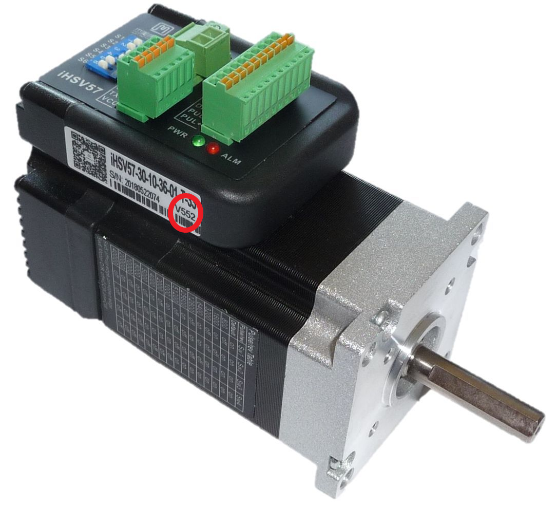
Tuning software is dependant on motor version seen highlighted in the below image.
V5XX:
Software: https://www.jmc-motor.com/file/1911133277.zip
Manual: https://www.jmc-motor.com/file/1806082788.pdf
Parameters:
When running the software run as an administrator.
Set the serial port configuration settings above in setting the communications port on the tuning computer. (On V5XX you are only presented the option of Port and Baud Rate)
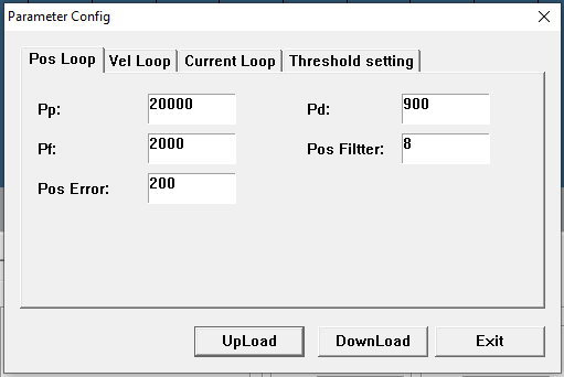
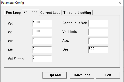
Each machine is individual so the parameters are likely to be unique to each users machine. However some basic parameters from Banchad's machine(Using 1610 ballscrews) will be included below for a baseline.
For the Y1 and Y2 motors the parameters can be copied over to each after tuning one of them on the X. So far this has not been an issue to operation
V5XX Parameters
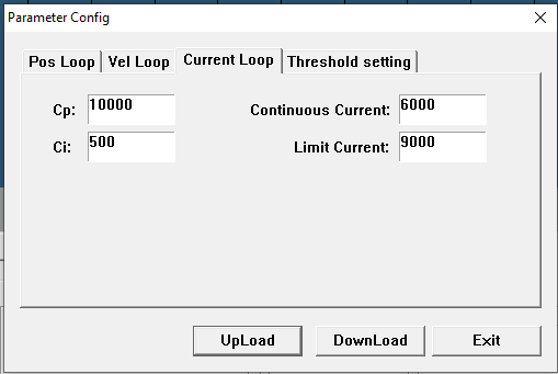
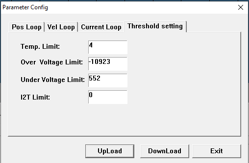
V6XX:
Software: https://www.jmc-motor.com/file/1911135649.zip
Manual: https://www.jmc-motor.com/file/2012025598.pdf
V6XX motors have the benefit of having an updated control software that has an autotuning parameter, P01-03. This should be all you need to modify to have a working servo motor driven axis.
Note: Increasing this parameter will result in a stiffer motor response but will also reduce the error before the motor trips out. IE using hypothetical imagined numbers, a rigidity setting of 1 could allow the motor to rotate 180 deg for 5 seconds before alarming and letting go, a rigidity setting of 31 could allow the motor to rotate 0.5 deg for 0.5 seconds before erroring out. It is up to you to decide how high a setting to set.

Other
Banchad has been having some issues with the AL.063 triggering the fault on his X gantry but this may be due to a deformed ballscrew nut demanding too much of the motor. A solution to this may be to use a pulley ratio of 2:1 which would make better use of the 0-3000rpm range of the servo while increasing the torque value of the system. with a 1610 ballscrew this would still leave the maximum speed at 15000mm/min. The tune on this motor may also be suboptimal.
Other resources:
DerNormio on youtube has a video series on the motor but it is in german and the autotranslate is sketchy.
https://www.youtube.com/channel/UCsrqtDzk1CRvbilYtEyzHpw
Nick P.
https://www.youtube.com/channel/UCSUfA3X5MkciSdX6st6r3EQ
Snagy