¶ Power Supplies
¶ The current recommendation for power supplies for the PrintNC 3.0 are Mean Well LRS-200-24V and LRS-350-48V (dialed down to 45V via the trim pot and tested with a voltmeter/multimeter). For a PrintNC Mini, the supply voltage needs to be chosen to match the stepper driver or integrated driver voltage capacity. The information about Cisco supplies below is no longer a primary recommendation due to increased costs, lowered availability, bulky size and power inefficiency.
These need to be chosen in tandem with the stepper motors and stepper motor drivers. [needs new links]
The amount of current that is going to be required to power all of the stepper motors needs to be calculated to ensure that the power supply is able to supply what is required. It is also worth adding an additional axis and some overhead to allow the machine to be expanded further down the line without the need to replace the power supply.
The power supply should also be able to supply close to the upper voltage of the stepper motor drivers that are chosen. If for example the stepper motor driver chosen is the TB6600, which has a maximum voltage of 42v, a power supply of 36v would be chosen. If the driver is rated for a maximum of 50v, a power supply of 42v would be chosen. This would result in the driver working at around 80%-85% capacity.
Also be aware that the controller used will probably require a different input voltage (5v for example), in which case, the appropriate power supply will also have to be sourced.
¶ Recommended Manufacturer
The go-to manufacturer for power supplies is Mean Well. They are known to supply good, reliable power supplies. Due to the amount of current that is required, it may well be found that more than one power supply is required to allow the necessary current to be produced.
Some of the PrintNC kits available through the affiliate AliExpress store include a “MW” 36V power supply, which is a Mean Well clone. This PSU is suitable for powering the Stepper Drivers. However, users frequently require additional voltages, such as 5V and 12V or 24V. Additional PSUs need to be sourced separately.
Some users opt to go for a slightly higher voltage than 36V for powering their Stepper Drivers and are also looking for a PSU with multiple outputs (rails with different voltages). See the Alternate Solution section below.
¶ A Note about Power Cords & Wire Gauge
¶ Q: What gauge cable should I use to connect my mains power to my enclosure? It will run from an outlet on a 110V, 15A, North American circuit.
A: Logan BC 🇨🇦: 12 AWG is 20A, 14 AWG is 15A, 16 AWG is 10A more or less. (PrintNC builders using higher voltage should adjust to their local power situations accordingly).
Q: I noticed the Cisco Catalyst 6500 PSU has an unusual power cable connection, what is the correct cord for using it in North America?
A: Trader: I ordered this one and it works fine: “Cablelera North American Power Cord Extension, NEMA 5-15P to C19, 10', 14 AWG, 15A, 125V (ZWACPFAC-10)” found here: https://www.amazon.ca/gp/product/B00GMPVALU/
¶ Frequently Asked Questions - PrintNC - Power Supplies
¶ Q - I'm curious why more PSUs targeted at industrial and CNC applications don't have 12V and 5V rails. A 36V/12V/5V supply with regular PC standard connections on the 12V and 5V rails seems like a really useful piece of kit. Likewise having that option in an ATX PSU form factor. Anyone ever seen that?
Logan: There are 12/5 and 24/5 combo supplies from meanwell.
¶ Cisco Info Archive for Existing Builds.
Another route to go down is to find a server power supply. The power supply is a Cisco WS-CAC-1300W or similar output in the series. These are able to supply up to 28A @42v (as well as 3.3v, 5v and 12v) and can be bought refurbished very cheaply. The voltage can be lowered or increased. Further information can be found here or by searching the Discord.
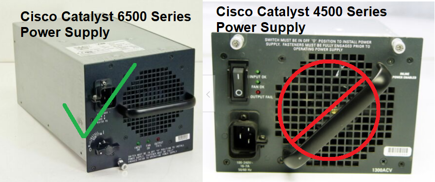
There are Cisco 4500 power supplies as well as 6500 series. The 4500 series ARE NOT suitable for a PNC power source.
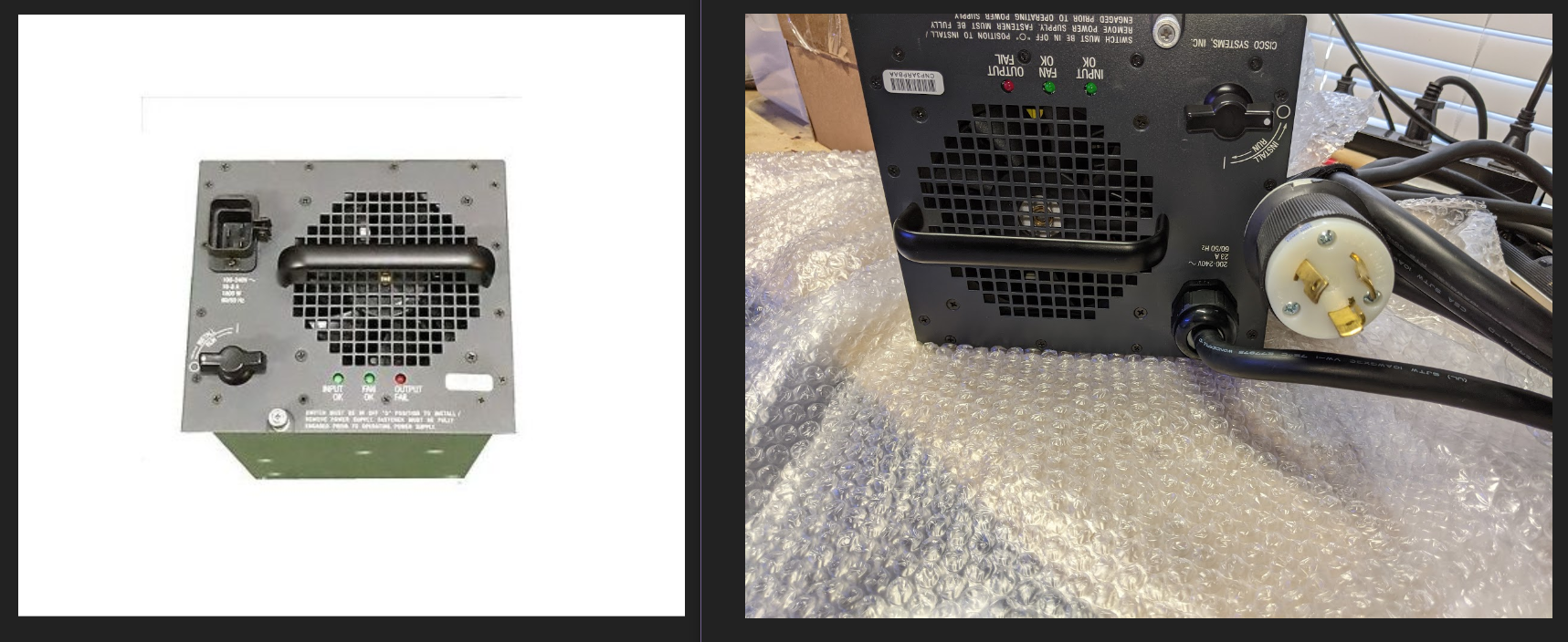
Be aware that there are different versions of the 6500. The Sony-branded versions have PCIe connectors going to the power board, so you can buy a PCIe splitter and you don't have to solder anything. For non-Sony branded versions, you can either solder the wires, or you can buy the fancy power connector that fits onto the back. Each pin for that connector is a couple of bucks, but you won't have to modify the PSU at all.
If you want to use PCIe split method, you can turn the device around and look for the white PCI-E connector through the ventilation grille. This is hard to do if you're buying it online, because they probably won't specify which version it is on the listing.
When ordering, be aware that some units include a fixed power cable that expect 220v. Units with a C19 connector are compatible with both 110v and 220v.
¶ Three Methods to Use any Cisco 6500-series to Power your Project:
- Cisco Connection Method (with power board)
- This works on Sony-branded PSUs.
- Cisco Connection Method (without power board)
- This works on any 6500-series PSU.
- Alternative Cisco Connection Method
- This works on any 6500-series PSU.
In Method #1 you open the PSU and connect a PCI-E connector. PCI-E connectors are easy to find.
In Method #2 you open the PSU and solder wires.
In Method #3 you connect to the back of the PSU using a special power cable. The power cable is available on Mouser, if you're in the US.
Cisco Connection Method (with power board)
A method for connecting the Sony CISCO WS-CAC-1300W Catalyst 6500 power supply is as follows:
Materials needed:
- ring-style crimp stakon connectors
- 1m/3ft each of Red and Black #10 or #12 stranded single conductor wire - for 42V and Gnd
- 1 - 6 pin PCIe power cable splitter - For 12V, 5V and Gnd (two pins each)
- 1 or 2 - 6 pin PCIe power cable extension
Turn the power supply upside down and remove the front cover (16 small screws, leave the 4 in for the fan) and disconnect the 3 cables (fan, LEDs and line voltage)
Disconnect the two small cables running from the top to bottom circuit board. Then flip it over, removed the 6 screws on top, and two on the sides and stand up the top for access to the rear board with the power connections.
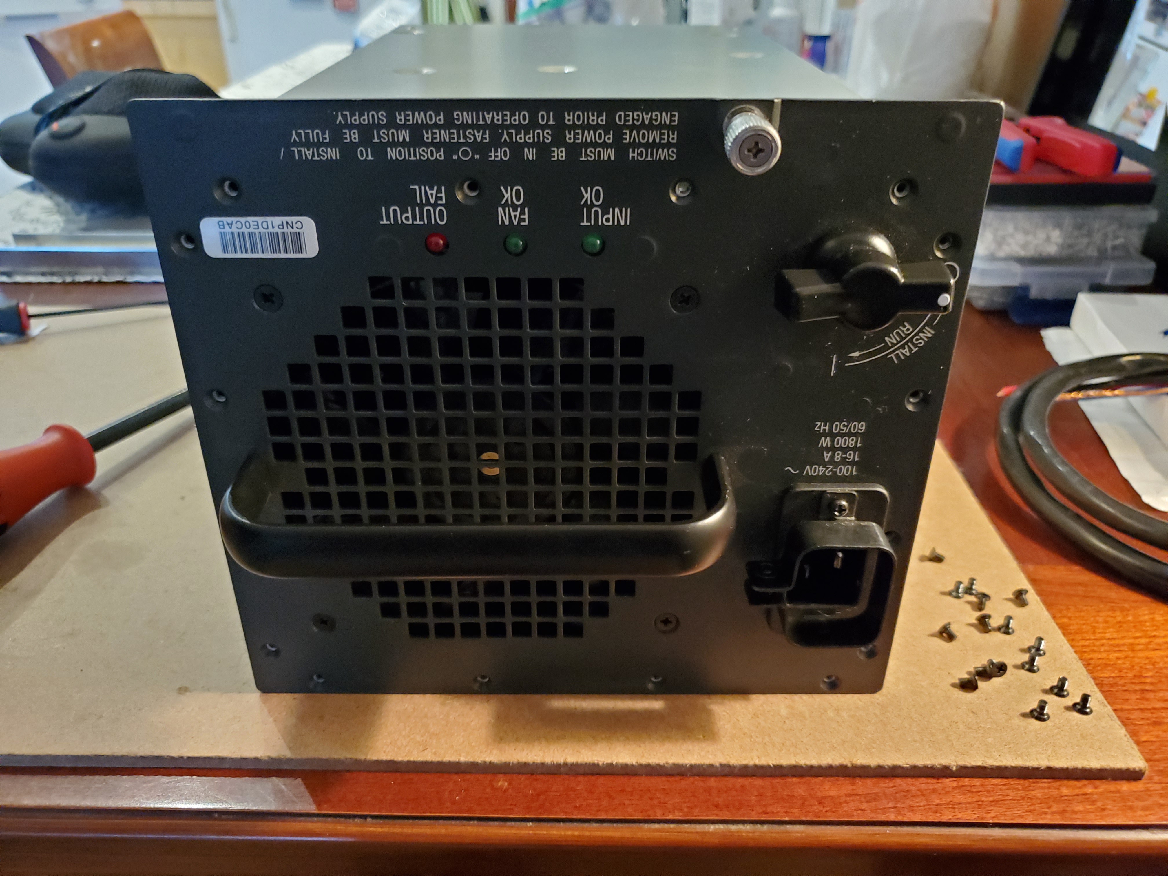
Remove the 4 screws to free the power connector board.
Connect the PCIe 6 pin power splitter cable. One end of the splitter goes to the input; it splits into two outputs. One output goes to the rest of the PSU.
Also on the power connector board, connect some #12 stranded wire (with ring/stakon crimped connectors) to the 42V and 42GND screws. On the pics below, these are the wires with the yellow sleeves. The ones that are double-stacked include the new connections on top.
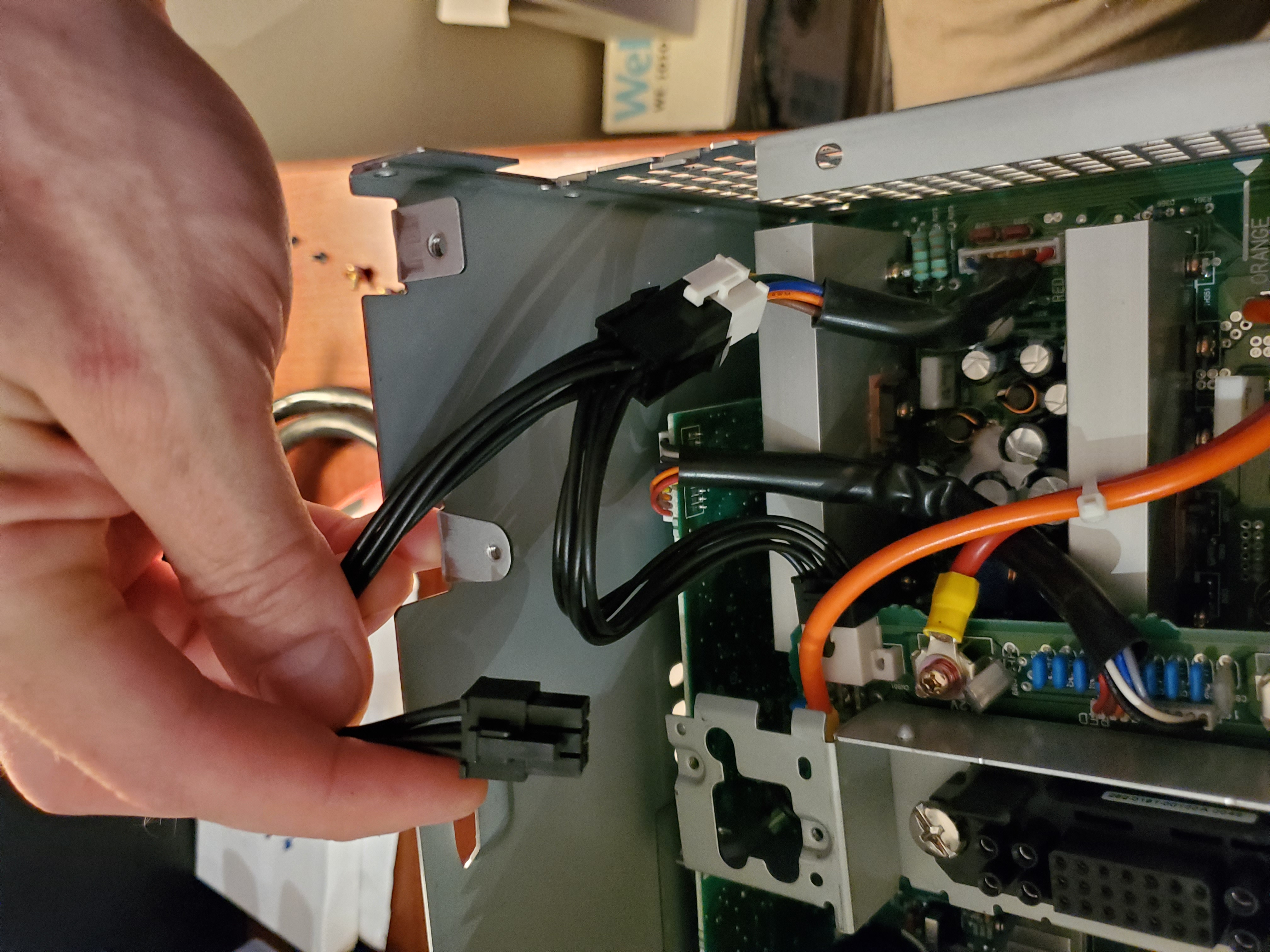
Run the 6pin connector and two #10/12 wires through the hole in the backplate and reassemble.
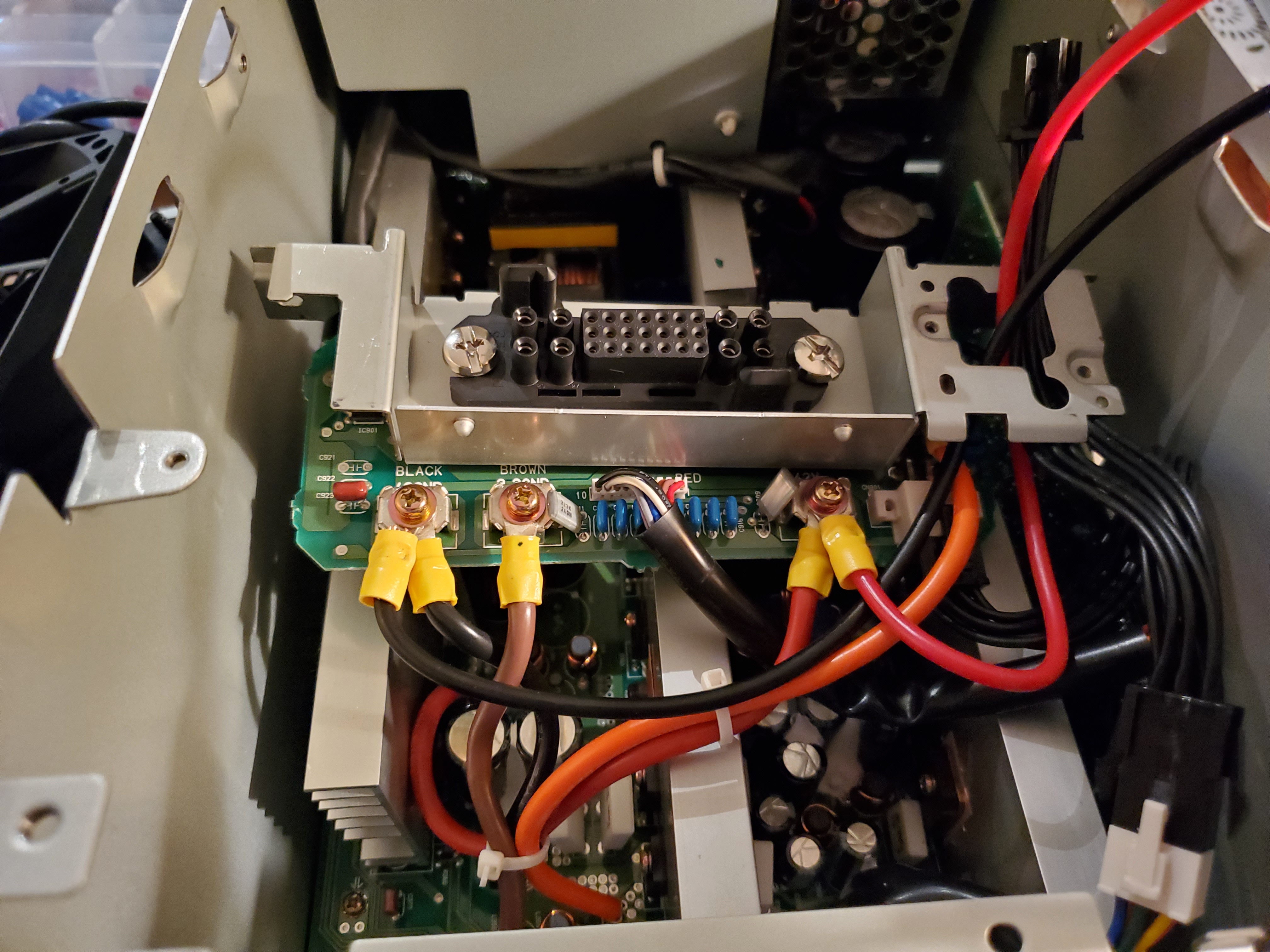
Ensure all the connectors are attached before putting all the screws in. The 6 pin splitter for the backboard, the two cables between the top and bottom circuit boards, and the three cables between the front plate and the top circuit board.
¶ Cisco Connection Method (without power board)
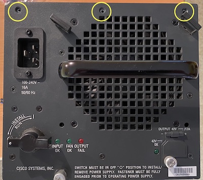
The Cisco version without the power board is rather easy to open. Just unscrew these screws in the front.
Then unscrew the ones on the bottom.
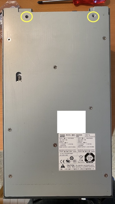
And now you push the bottom towards the back a little to unhinge it. To remove the control board on the bottom you have to remove 4 connectors.
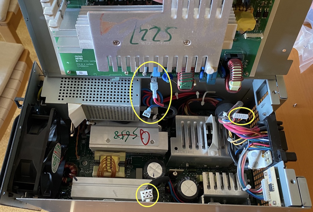
Given this Cisco does not have a power board with the connector you only got two options. Either go with the official plug (see below) or cut the wires on the back of the connector.
¶ Alternative Cisco Connection Method
It is possible to connect directly to the back of the Cisco power supply with parts purchased either from Digikey or your local electronics supplier.
The parts needed are as follows:
- CONTACT PIN POWER 20AWG GOLD - https://www.digikey.com/en/products/detail/1650155-1/A36285-ND/1636349 (Qty: 2)
- CONTACT PIN POWER 12AWG GOLD - https://www.digikey.com/en/products/detail/1650153-2/1650153-2-ND/2258954 (Qty: 4 [5 if you want 3.3V as well])
- CONN PLUG HSG DRAWER 29POS BLK - https://www.digikey.com/en/products/detail/1648203-1/A36262-ND/1636326 (Qty: 1)

These pins can either be crimped or soldered.
--
In addition to the Drawer and Pins, you may want to purchase the insertion/extraction tools as well. These are available on both Digi-Key and Mouser, and probably other resellers as well.
The part numbers for the extraction tools are:
- Size 12 insertion/extraction tool: 1643915-1 (eg: https://www.digikey.com/en/products/detail/te-connectivity-amp-connectors/1643915-1/1636374) (Qty:1)
- Size 20 insertion/extraction tool: 1643917-1 (eg: https://www.digikey.com/en/products/detail/te-connectivity-amp-connectors/1643917-1/1636372) (Qty: 1)
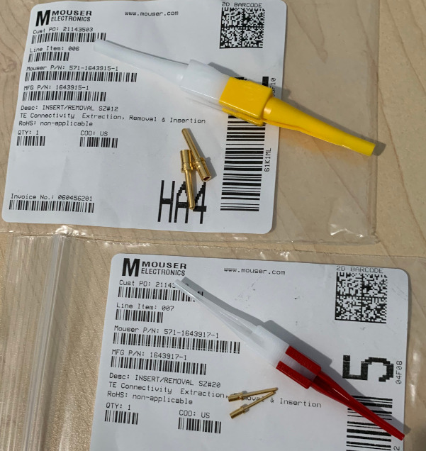
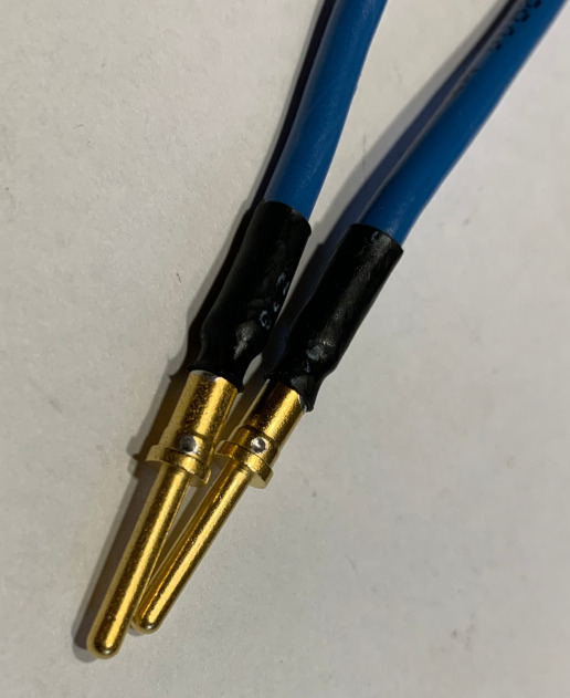
For insertion, usually pushing the wire+pin works, if the wire itself is sufficiently stiff. For removal though, the tool makes the task really easy. Just try not to get much solder on the barrel part of the pins. Also, if using heat shrink tubing to protect some exposed wire, be careful not to overlap the barrel with heat shrink, as it may prevent the extraction tool from working correctly.
--
RS Components has some but not all of the pins available as well.
tcurdt: There is another option for those pins that are not available anymore - but I don't have their number anymore. These are for ordering as an individual :
https://www.rsonline-privat.de/Products/ProductDetail/TE-Connectivity-ELCON-Steckverbindergehause-Male-29-polig-Gerade-fur-Stromversorgungssteckverbinder-7195082
https://www.rsonline-privat.de/Products/ProductDetail/TE-Connectivity-ELCON-Drawer-Crimp-Anschlussklemmenkontakt-Male-Crimpanschluss-fur-Elcon-Drawer-Steckverbindergehause-7121520
https://www.rsonline-privat.de/Products/ProductDetail/TE-Connectivity-ELCON-Drawer-Crimp-Anschlussklemmenkontakt-Male-Crimpanschluss-fur-ELCON-Mini-Drawer-Lower-Drawer-7195098
Or these when ordering as company:
https://de.rs-online.com/web/p/steckergehause-und-stecker/7195082/
https://de.rs-online.com/web/p/crimp-kontakte/7121520/
https://de.rs-online.com/web/p/crimp-kontakte/7195098/
--
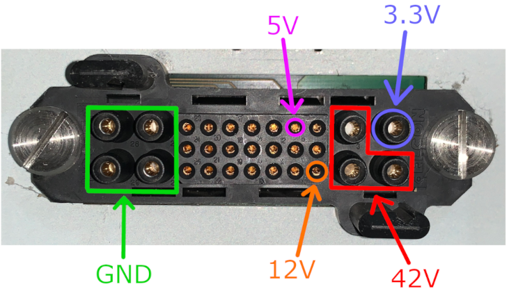
The pinout of the connector is as follows. Please note that a previous version of the pinout diagram was published here in the past and contained additional 5V and 12V size-20 pins, which do not work correctly (voltage drops when current is pulled on these pins or in some cases, the PSU goes in Fault Mode when current is pulled)
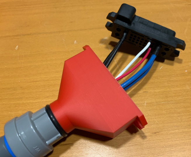
Here is Flukester QC 🇨🇦's completed connector. Note that the printed outer shell (red) is a design by Rpatterson and is available in the https://wiki.printnc.info/en/mods page.
