As of 2023 the recommended board for running a PrintNC is the Flexi-HAL, which was the successor design to the GRBLHAL2000 EST (Electronics Standardisation Team) controller. Both boards have similar overall functionality and input/output.
¶ Tools and Parts
There are some tools and parts needed to successfully wire up and configure your GRBLHAL2000 to run a machine. At a minimum you will need the following:
- PC running sender software. A Windows PC running ioSender is suggested for initial setup as ioSender has the best integration with grblHAL. Once you're up and running you can use the grblHAL-compatible sender software of your choice.
- Flexi-HAL or GRBLHAL2000 board, flashed with the correct firmware: Check with your board supplier if it's pre-flashed.
- Data-capable USB-C (Flexi-HAL) or micro-USB (GRBLHAL2000) cable for connecting to the board. For simplicity on a GRBLHAL2000 it is suggested you start with a USB/serial connection, then switch to an Ethernet connection once you start working on VFD control. The Flexi-HAL is a fully isolated design, so it doesn't require an ethernet connection to the sender PC for reliable operation with a VFD.
- 12-24V DC power supply: Both boards require external DC power. 24V is recommended (more details on the official github)
- Stepper cables: 8-conductor IDC cables, though unless you're running servo motors only 4 conductors are generally used
- Ethernet cables: For User Switch and Sensor breakout boards. As the sensor breakout runs through a cable chain, flex-rated or at least stranded ethernet cable is recommended.
- User switch should reach from your enclosure to the main operator position
- Sensor breakout should reach from your enclosure and run through the Y axis cable chain to a breakout position where the 2 cable chains meet
- Limit sensors: Generally 4 are used: X min, Y1 min, Y2 min, Z max. Parametric mounting solution.
¶ Information:
¶ Flexi-HAL Board diagram
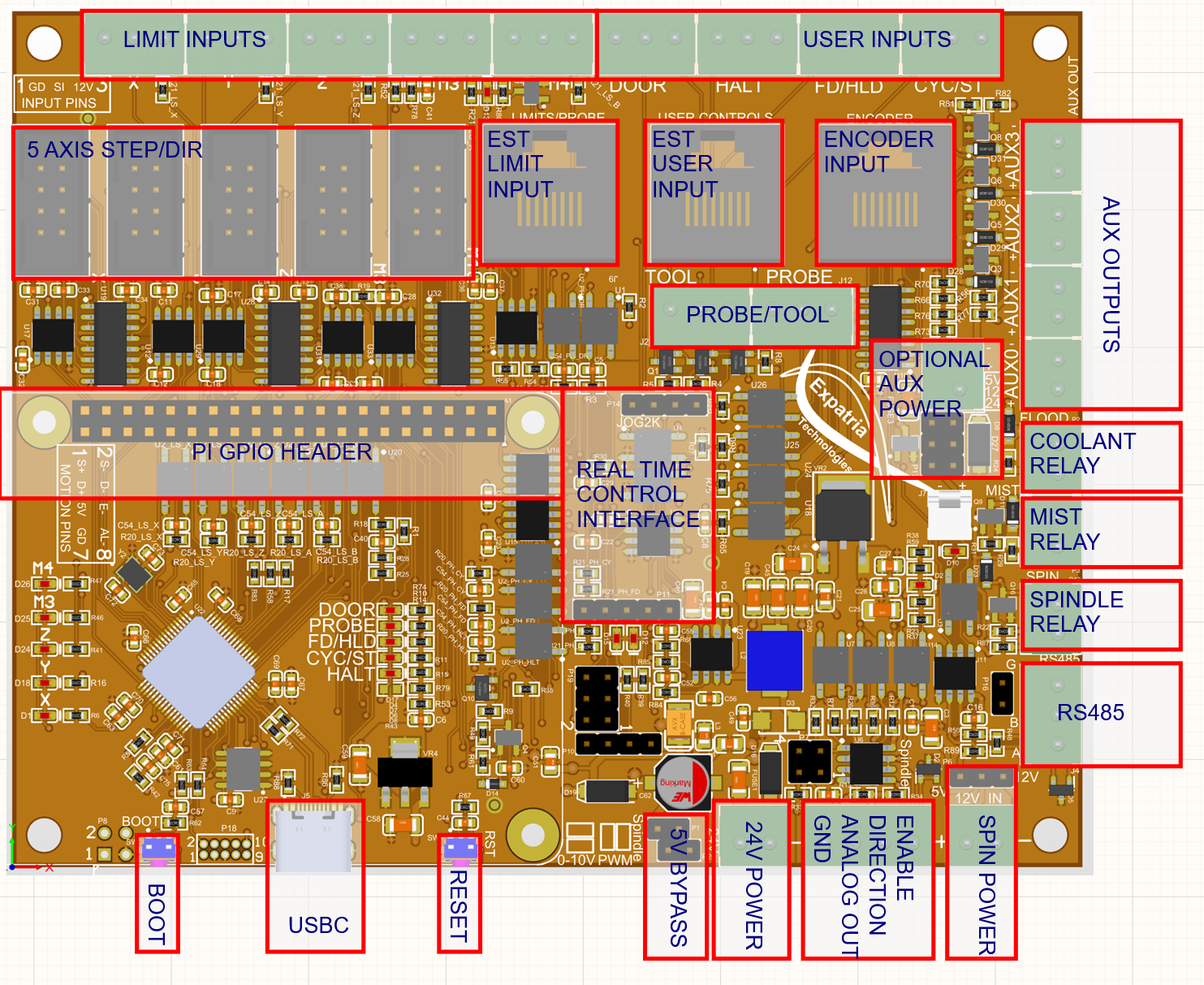
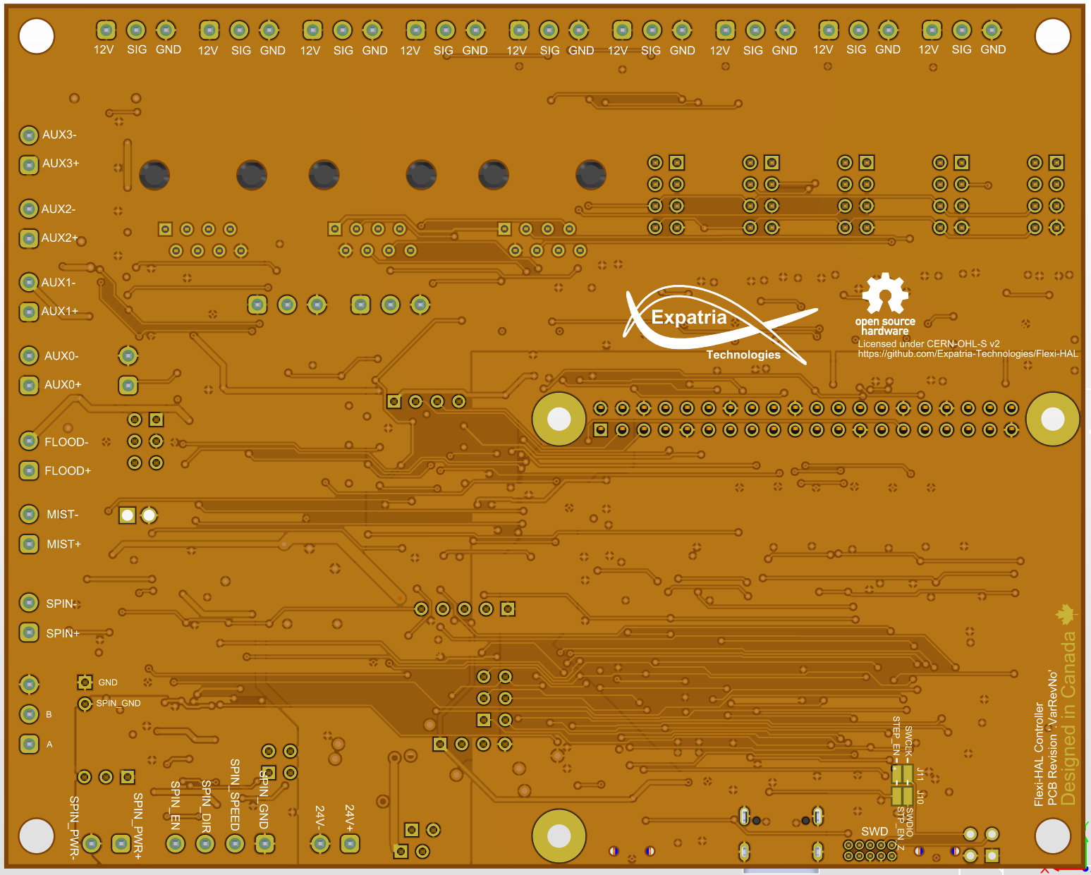
¶ Flexi-HAL bottom side silkscreen labels
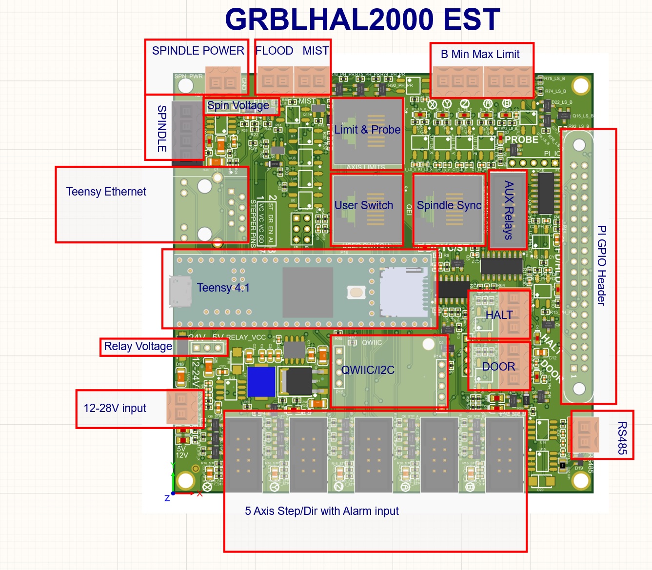
¶ GRBLHAL2000 EST Board diagram
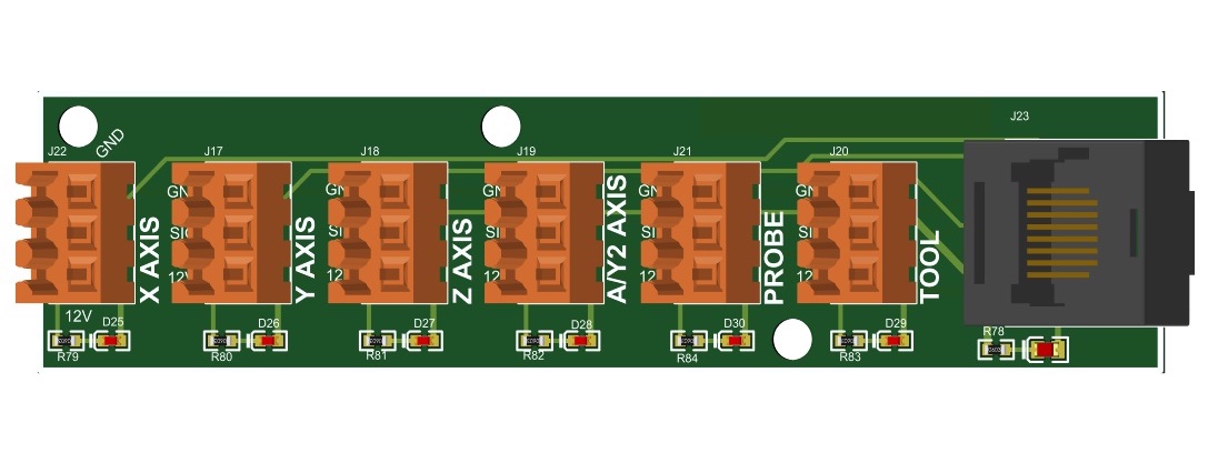
¶ EST Limit Sensor and User Button breakout boards
These boards are connected with RJ45 (ethernet) cable to the Limit and Probe and User Switch sockets labelled on the image above. The Limit and Probe breakout should be mounted on your X-axis gantry, and the user switch breakout can be mounted to your enclosure or used as a handheld pendant for estop etc.

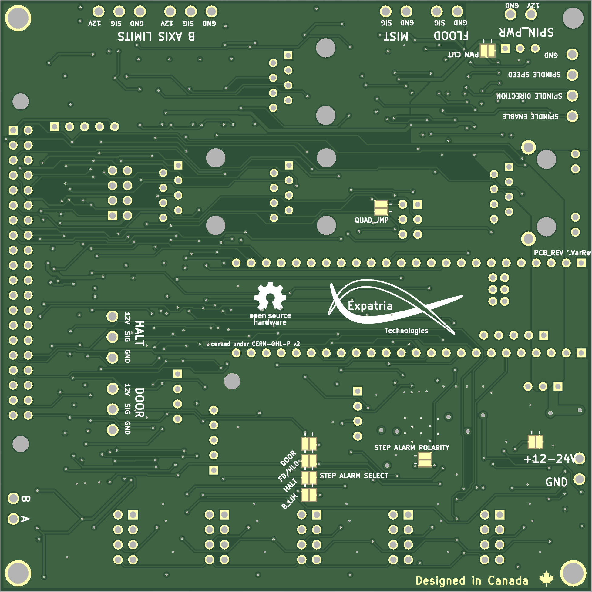
¶ GRBLHAL2000 EST bottom side silkscreen labels
¶ GRBLHAL2000 Board Diagram
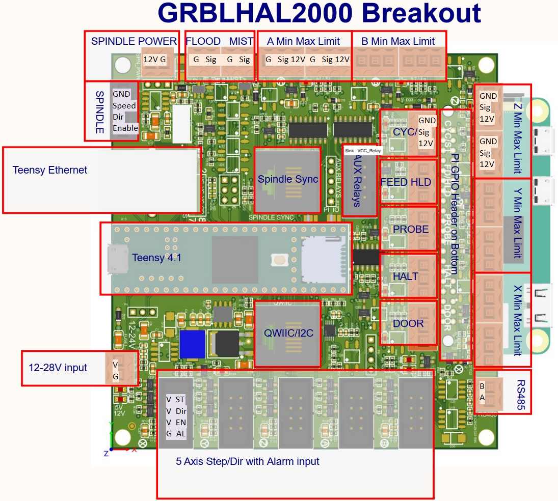
The above board orientation with the Teensy USB connector to the left is used when referring to directions (top, middle, bottom, left, right) in the following instructions.
¶ Flexi-HAL or GRBLHAL2000 Wiring Process
Everyone's machine setup will be slightly different, but the general components to get wired up are:
¶ Core Functionality
The components and connections that most builds will use:
- Stepper drivers
- Limit sensors
- Control buttons (Cycle/Start, Feed Hold, EStop/Halt)
- Spindle Control
- RS485 if your VFD is supported
- Analog spindle control if your VFD isn't supported
- Board power supply - 12-28V DC
- USB/Ethernet connection to sender PC - for inital setup USB is recommended. If controlling a VFD, ethernet is suggested as it's less succeptible to electromagnetic interference.
¶ Optional Functionality
Not necessarily required to get your machine up and running, but great to have:
- Flood/Mist coolant outputs - control solenoid valves for compressed air and lubrication
- Aux Relays - can control RGB status LEDs, Probe/Tool setter selection relay, or anything else which can be automated with a switch
- Door Sensor - additional safety interlock for enclosure door
- QWIIC/I2C - keypad jogging and control pendant
¶ 12-24v board power supply
The GRBLHAL2000 takes external 12-24V DC power to supply voltage to board components as well as limit sensors and to power relays.
¶ Motors
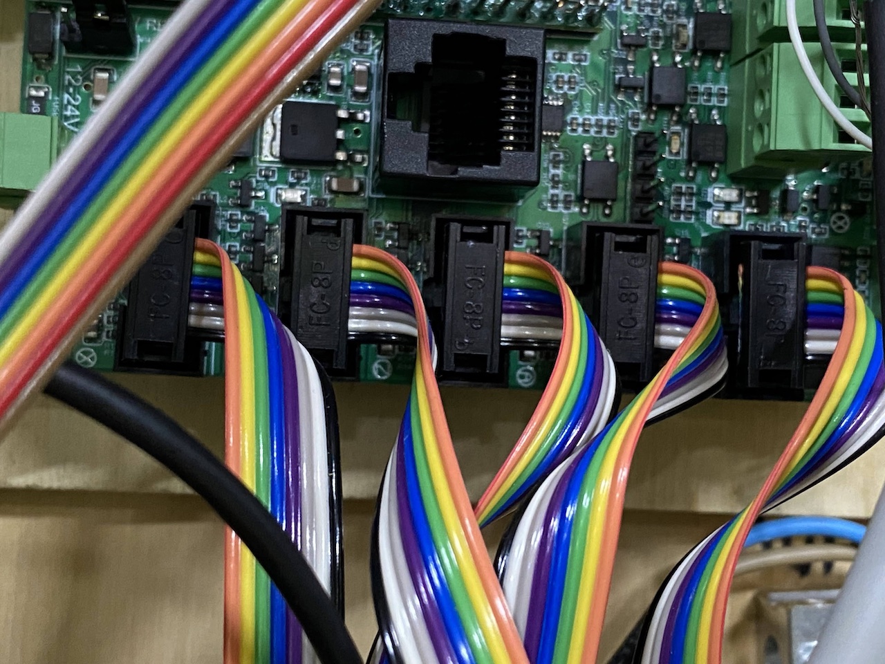
Each stepper connection (X, Y, Z, A (Y2 on dual-Y axis PrintNC machines) B) uses an 8-pin IDC cable (pinout below) for Step, Direction, Enable, and Alarm.
For “standard” open-loop steppers it is recommended to just use Step and Direction as disabling the drivers will cause your motors to lose microsteps and potentially move your gantry out of square or lose presision.

For a PrintNC or other dual-Y CNC machine you connect X, Y (Y1 - Left side Y motor), Z and A (Y2 - Right side Y motor) from the board to your stepper drivers.
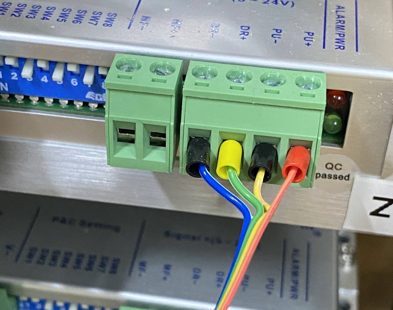
- Stepper ICD Cable PINOUT:
- VC to PUL+ (5V)
- ST to PUL-
- VC to DR+ (5V)
- DR to DIR-
- VC to EN+ (5V) (Not recommended/required for open-loop steppers)
- EN to EN- (Not recommended/required for open-loop steppers)
- GND
- ALM+ (Alarm output for closed-loop or servos)
The below images show ribbon cables installed in the IDC sockets (pin 1 at the top), and the corresponding colours going to a stepper driver.
¶ Ensure drivers are set to 5V logic
If using DM542T V4 drivers they will default to 24V logic from factory, flip the switch on top of driver to change to 5V.
DM542T V2.3 are 5V logic by default
¶ Connecting Servos
Servos use the above wiring along with Alarm. To enable the alarm signal one of the Step Alarm Select solder jumpers on the underside of the board should be bridged.
¶ Limit Sensors
¶ Button Inputs
start/hold/estop
¶ Probe and Tool Setter
¶ Spindle
¶ Coolant
Flood and Mist outputs
¶ Mounting board to enclosure
- printable mount options
- Logan hal2k stl files
- hole spacings