¶ Endstop types
There are many different types of endstops that can be used on the printNC.
They can be either contact (requiring two parts of the frame to touch) or non-contact.
Unless repeated homing of the spindle during operation is required, the accuracy of the endstop is not critical. Some examples are below
¶ Inductive Sensors
These are the standard LJ8A3-2-z/AX sensors included in the aliexpress kit.
Inductive sensors use a magnetic field to detect objects and will therefore only work with metal items.
¶ Do Inductive Sensors work on aluminum?
“Yes, standard inductive sensors can sense aluminum but the range is decreased, usually achieving about 40% of the rated range using a standard target made of ASTM A36 mild steel. The one exception is aluminum foil [<0.1 mm] which makes an excellent target. This is due to an obscure principal known as the ``skin effect``”[source]. “Alternatively Many sensors exist today that can detect ferrous and non-ferrous models at the same distance. These are sometimes known as “Universal” or “Factor 1” sensing types” [source].
They come in both NPN and PNP. The NPN are better for the BOB, but if you have a mesa you need ones that match your type, active high or active low inputs. "I used PNP-NCs because I wanted everything NC, but it meant that to save BOB inputs I needed to make a circuit board with an AND chip (CD4082BE). One downside to sharing inputs is that you have to have all the sensors untriggered when you start your homing".
¶ Cost:
“Maybe a $5 a sensor”
"I paid 1,90€ each"
"LJ12A-3s are more like $1 ea before shipping"
¶ Other Endstop types
¶ Microswitch - Contact
A simple but very effective form of endstop. A recommended manufacturer is Omron.
It is recommended that you use the normally-closed contacts of the microswitches, which are generally the outside two connections on the microswitch. This is to prevent interference, leading to false triggering of the endstops.
¶ Hall Sensors - Non-contact
These use magnets attached to the moving part of the frame to trigger a reed switch when nearby. These are available in both 3.3v and 5v.
¶ Optical Endstops
Use a "flag" attached to the moving part of the frame to break an infrared beam. These are available in both 3.3v and 5v.
¶ Capacitive Sensors
These use an electric field to detect objects and will work with both metal and non-metal items. They come in both NPN and PNP.
¶ FAQ Homing and End-Stop / Limit Switches
¶ Q – What are homing switch and how are they different from limit switches?
Homing switches help the machine locate its home position when it is powered on. Limit switches detect the maximum and minimum travel on a given axis.
¶ Q – What is homing and why is it so important?
It is helpful to know that the conceptual X, Y and Z distances in the gcode system are technically infinite. In this way a machine of virtually any size can be built. For example, a boat building company near me has a 5' x 30; foot CNC they use to cut aluminum boat hulls on.
At power on, your CNC machine can not be certain where the spindle is in real space, as it could have been moved for any number of reasons, while the controller was disconnected, including it being the first time you ever power on after building the machine.
More typical examples of the machine “losing position” or “crashing” are that you have a bit jam, you crash into the end of your range of travel in an axis or otherwise lose your position due to human error or mechanical failure.
Homing is how the machine finds it’s physical starting point in the conceptual 3D grid that represents the XYZ work area of your CNC.
¶ Q – How does the homing sequence work?
During the homing sequence, the machine attempts to establish the maximum travel in one direction on each axis. By convention, CNCs (and the gcode they process) operate in the -X, -Y, -Z space, the lower left quadrant of a conventional cartesian quadrant grid.
Homing involves finding maximum positive travel in each axis, so the homing process involves raising the spindle to Zmax height and moving the gantry to Ymax (rear of table) and over to Xmax (right side of table). The result is the theoretical 0,0,0 position on the four quadrant grid, and physically appears as your spindle being in the right rear corner at full height. This is why many photos of idle professional machines have the spindle parked in this position.
¶ Q - Why are there so many different versions of inductive limit switches? What do NO, NC, NPN and PNP mean and how does that affect my limit switch design for my PrintNC CNC?
The inductive limit switches that most PrintNC users have on their machines are able to detect the approach of metal towards the sensor at a very precise distance and with good accuracy. Sensors of this type are very common in industrial machinery. Inductive proximity sensors are meant to be non-contact in that they trigger their alert without requiring physical contact with the surface they detect.
NOTE: To determine what type of switches you need, consult your controller or breakout board documentation. NPN NC style switches are a good choice if you need to get your order placed from overseas and can not determine what type to choose.
So what do the various abbreviations mean?
NO switches are “normally open”, which means that a sensor event will close the switch and complete the circuit. For this reason, NO style switches must be wired in parallel since the circuit is not complete unless it is in alarm state.
NC switches are “normally closed”, which means that a sensor event will open the switch and break the circuit. For this reason, NC switches on an axis must be wired in series with either switch able to trigger the alarm on the shared input pin on the receiving end of the signal. Likewise, if an NC switch fails during operation or passively when the machine is not in use, that failure will usually break the circuit and throw an alarm, alerting you that your end stop and homing system may have an issue.
NPN and PNP describe whether the sensor pulls the signal line to the high voltage or to ground.
When triggered, NPN switches switch the ground connection from their power and ground input lines to the signal line, pulling the connected signal pin on the receiving end to ground. This will require the receiver to have an internal or external pull-up resistor in order to be in a high state (binary +1) as the default, so it gets pulled to ground (binary +0) when the alarm signal arrives. This makes it very flexible and largely eliminates any relationship between the voltage used to power your sensors and the supported voltage range on your controller or breakout board.
Conversely, PNP switches when triggered, switch the +V voltage from their power and ground inputs on to the signal line, pulling the connected signal pin on the receiving end high (binary +1) to the voltage of the input power signal. This means that the receiving pin for the signal line must be voltage tolerant up to the voltage that you will be supplying to represent the signal event. PNP switches are therefore considerably less flexible and require additional safety and planning considerations. If you purchased PNP switches for your PrintNC, ensure your breakout board or controller can handle input signals at the voltage you intend to power them with.
¶ Q - How do I wire NPN NC sensors to my Mesa 7i96 inputs for the the end-stops and homing?
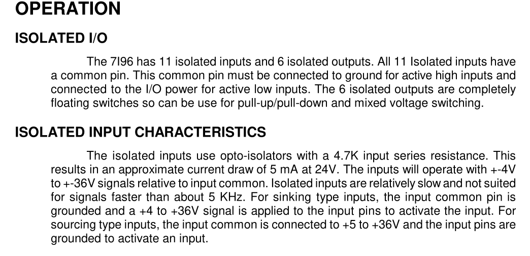
Because NPN sensors pull the signal line to ground, you want the difference between the signal and the V+ line, therefore you want the input common pin to be connected to the V+ rail of your sensor power circuit.
For example:
I have a 12V+ supply that I am using for my sensors. I have NPN NC sensors. The connections (double check wiring diagram on your sensor, but this is typical):
Sensor brown wire → 12V+ power
Sensor blue wire → GND- (from 12V circuit)
Sensor black wire (signal) → Mesa Input #x
At the Mesa 7i96 the common input pin is connected to the same 12V+ power that the brown line of the sensor is wired to.
When triggered, the NPN NC sensor pulls the signal line to ground, which can be confirmed by using a multimeter and connecting your +/Red connection on the meter to the 12V+ and your common/black probe to the black signal line. When the sensor is not tripped, you will see ~12V, when you put some metallic in front of the sensor and trip it, you should see your meter drop to almost 0V.
Many of the inductive sensors have an LED light. For an NPN NC sensor, the light is light when there is NOT a triggering event and it will go dark when you trigger the sensor (indicating the circuit has been broken). On a previous machine I had PNP NO sensors. They operate in an inverted way and are normally dark and they light up when triggered and the voltage, as that close the circuit and apply voltage to the signal line.
If you know you have an NPN NC sensor and it doesn't go dark when triggered, then you do not have your wiring set up correctly. I was getting trigger events at the Mesa when I had the common connected to GND, but when measured on the meter I was only dropping from ~12V to ~7V when triggered and the light was not going out. Changing the common to +12V (as indicated in the manual) resolved the issue.

¶ Q - My sensor is not labeled, how can I test whether it is NPN or PNP type output?
A good article on how to test your sensor, depending on the type, can be found here: http://automation-and-controls.blogspot.com/2009/02/how-to-test-whether-sensor-has-pnp-or.html
¶ Q - Anyone have a mechanical switch mod that doesnt sit inside the BK/BF and can be machined (no 3d printing)? Could be for the push buttons or the bigger blue ones. I don't want to have to rewire everything for inductive sensors
Logan: You can mount a mech switch facing down on back of X and sides of Y rollers and use angle brackets to trigger it. That way it's min and max in one switch. But you'll have to mount your cable chains above
NeoKurtex: I'm looking at what joeyp did. i think it might work
.png)
rcw: The easiest machining way I can think of is to drill holes in angle brackets (or angle aluminum) and mount inductive sensors.
NeoKurtex: my issue with inductive sensors is i didnt set up my system for it. my wiring is arleady done for switches (2 wire isntead of 3) and my optoboard i made is only 5v.. switches are just a lot easier. not in any mood to solder gx16s again
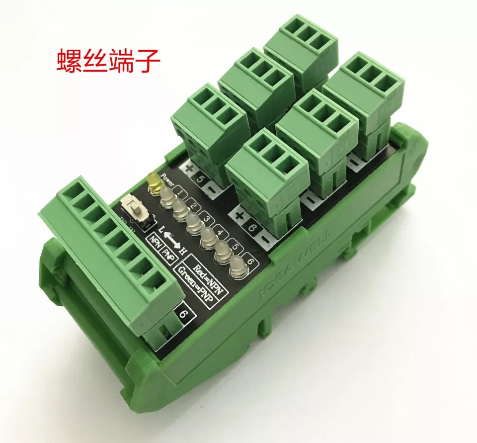
Logan: This is pretty slick. Run a cat5, mount it on your gantry, 6 sensor connections plus 24V and ground.

NeoKurtex: What is that called?
Logan: C$ 16.60 | 6-way Proximity Switch Sensor Terminal Block Two-wire Three-wire PLC Input Module Photoelectric Conversion Board NPN / PNP - https://a.aliexpress.com/_mPW4KBR