¶ PrintNC Wiring and Electronics Enclosure
Contained in this section of the wiki:
CAD file for the components, panels, wiring and labels: github CAD link
Electrical components build of materials
optional kit for a 2020 based DIY enclosure
wiring length calculations and descriptions for cabling from enclosure to steppers, spindle and sensors
Enclosure AC wiring Diagrams
Enclosure DC wiring Diagrams
Enclosure Control wiring Diagrams
Wiring from Enclosure to PrintNC Steppers, Spindle and Endstop Sensors.
Older Wiring and Enclosure pages are still available as archived documents.
https://wiki.printnc.info/en/v3/wiring-archived
https://wiki.printnc.info/en/electronics/enclosure
¶ BOM:
¶ Option 1: Manufactured Electrical Enclosure
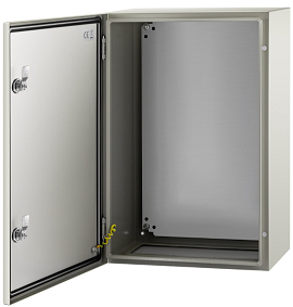
You can order new or used electrical cabinets from ebay, vevor etc. Minimum size 16x24x8" or 400x600x200mm.
- 40 - M4-0.7x6mm button head bolts (for din rails, drivers, and wire ducts)
- 4 - M5-0.8x8mm button head bolts (for VFD)
Recommended tools for adapting the enclosure to the DIY custom plates and fan mounts:
- Jigsaw, angle grinder or dremel
- 1" or 25mm carbide hole cutting saw
¶ Option 2: DIY Enclosure using 2020 T Slot Extrusion and aluminum, steel or ACM panels
¶ Frame:
2020 T-slot Extrusion
- 4 - 200mm
- 4 - 360mm
- 4 - 560mm
¶ Panels:
3mm aluminum or ACM panels
- 2x - 200x400mm
- 2x - 200x600mm
- 2x 400x600mm
¶ Fasteners:
- 50 - M5-0.8x8mm button head bolts
- 40 - M5-0.8x16mm button head bolts (For Misumi extrusion. For EU standard, 8 need to be M6-1.0x16 instead)
- 12 - M5-0.8x6mm button head bolts
- 48 - M5 roll-in Tnut
- 30 - M5 hex nut
- 48 - M4-0.7x6mm button head bolts
- 4 - M4 Tnut
¶ Hardware:
- 560mm/22.5" - Piano hinge cut to length - 38mm or 1½" (flat width), 20mm 13/16" (folded width)
- 2x - cabinet door magnets
- 1.5m/5ft - 20x6mm or 3/4x3/8" foam strip - for door seal, can also be used for fans or power supplies to reduce noise.
¶ Electrical Components:
- 1 - 2P 30A lighted toggle switch - JD03-A1 https://www.aliexpress.com/item/32957666162.html
- 1 - ABB AF09-30-10-13 100-250VAC coil Contactor
- Alternate: Schneider 3P LC1D25 (220V coil)
- 1 - 1 to 5A 250V din rail breaker or 250V rated fuse
- 1 - Estop (220V, 2NC) switch https://www.aliexpress.com/item/1005005433584606.html
- 1 - Red Stop (220V 1NC1NO Momentary self-reset) Switch https://www.aliexpress.com/item/1005005406999292.html
- 1 - Green Start (220V 1NC1NO Momentary self-reset) Switch - same link as above.
- 1 - FlexiHAL controller (or equivalent) https://expatria.myshopify.com/products/flexi-hal
- 4 - DM542T Stepperonline Stepper Drivers https://www.omc-stepperonline.com
- 1 - HY01 VFD (or equivalent) - YL VFDs are not recommended due to quality control issues and difficulty with RS485 setup.
- 1 - Meanwell LRS-350 (or RSP-320) 48V Power Supply (or larger if using 4x 5A steppers - 450W recommended) https://omc-stepperonline.com or https://www.aliexpress.com/item/4000364274787.html
- 1 - Meanwell LRS (or RSP) 100-200W 24V Power Supply https://omc-stepperonline.com or https://www.aliexpress.com/item/4000364274787.html
- 2 - 24V 120mm Fans
- 2 - 120mm fine mesh fan filters
- 1 - 20A Line Filter with spade terminals
- 6 - Wago 221-415 lever connectors
Optional: Various PCBs to simplify wiring. Contact Logan BC CA on discord or order from jlcpcb.com. Details, source files and CAM files here: https://github.com/LoganFraser/PrintNCMods/tree/main/PCBs
¶ Wires:
- (various length) 1.0mm^2/18-4 double shielded, continuous flex cable from VFD to spindle CF10 https://www.igus.com/ or CF27 https://www.igus.com/ or https://www.automationdirect.com
- (various length) 1.0mm^2/18-4 or 0.5mm^2/20-4 (shield optional) continuous flex cable for stepper motors https://www.igus.com
- (various length) Cat5e/6 ethernet patch/flex cable from controller to sensor breakout pcb (stranded only)
- 60cm/24" - twisted pair from Flexihal to VFD for RS485
- 7.5m/25ft ea - 0.5mm^2/20AWG solid core hookup wires: set of red, black, blue, white, yellow, green
- 1.5m/5ft ea - 1.5mm^2/16AWG stranded core hookup wires: red, blue, green.
- 2-3m/6-10ft - 1.5mm^2/16AWG standard computer cord - cut off the C13 socket end.
- 50cm/20" - 5x2 IDC cable from VFD to Control Panel (use with 1 end rotated, or pull the socket off the display and rotate 180 degrees).
¶ Wire Length Estimations:
(distance from controller to rear corner of machine + 30cm or 12")= X
X + (frameY + 30cm or 12")           for Y1-Motor cable
X + (frameX + frameY + 30cm or 12")  for Y2-Motor cable
X + (frameY + 60cm or 24")           for X-Motor  cable and Cat5/6 ethernet cable for Endstop Sensor Breakout PCB.
X + (frameX + frameY + 90cm or 36") for Z-Motor and Spindle cables.For less frequent usage machines (under 10hrs per week) search Aliexpress for TRVVP Cable for spindle and steppers. Example: This is also available in multiconductor (3p or 4p twisted) for endstop pcbs and closed loop stepper cabling.
¶ Other Parts:
- 2m - 1" or 25mm width wire duct
- 2x - 250mm steel din rail
- 2x - M20 cable glands https://www.aliexpress.com/item/1005003093251442.html
- 5x - 5pin panel mount 3.81mm removable screw terminals (for driver to enclosure) https://www.aliexpress.com/item/1005004913297066.html
- Optional for Closed Loop Steppers - 5x - 7pin panel mount 3.81mm removable screw terminals (for driver to enclosure) https://www.aliexpress.com/item/1005004913297066.html
- 5x - 4pin 3.81 removable screw terminals (for stepper end) https://www.aliexpress.com/item/1005003053333839.html
- kit - Ferrules and crimper https://www.aliexpress.com/item/1005005790898161.html
- insulated female spade connectors (red for 1.5mm^2/16awg, blue for 2.5mm^2/14awg)
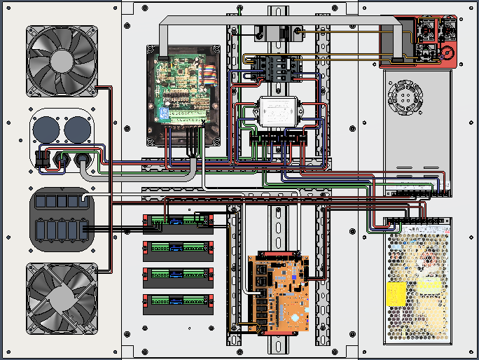
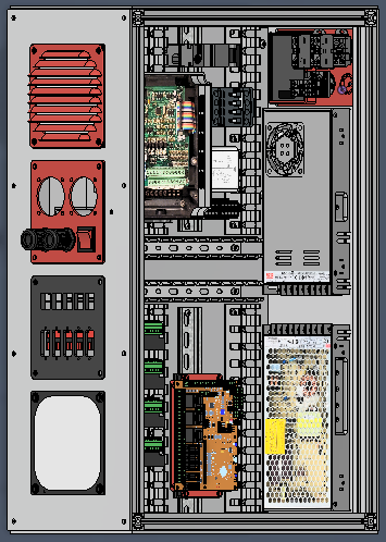
¶ Enclosure Wiring Diagram with Labels:
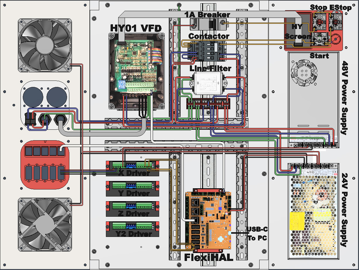
¶ AC Wiring Section:
¶ Incoming AC to Contactor wiring:
Wire the power cord to switch, from switch to contactor L1 L2, from contactor T1 T2 to wagos, ground from cabinet bolt to wagos. Connect wires from contactor L1 to 1-5A breaker, and L2 to A1 (coil contact)
Use 1.5mm^2/16AWG stranded core hookup wires, with insulated blue female spade connectors for power switch, ferrules for screw terminals, bare wire for wagos.
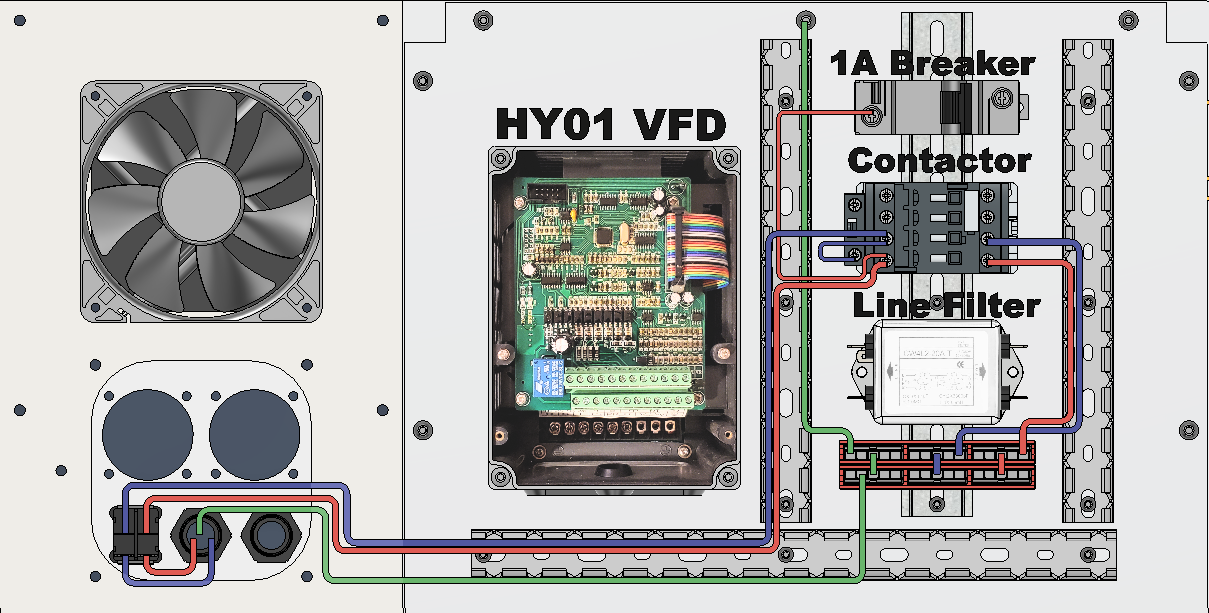
¶ Contactor control circuit:
Note: the 1A breaker is to protect the wires run from the start/stop buttons to the contactor coil so a smaller gauge wire can be used for easier wire routing. It is only to protect the wires and control circuit - this breaker is not protecting anything else. Your electrical panel breaker is for everything else in the electrical enclosure.
Connect wires: from 1A breaker to bottom of NC Stop, from top of NC Stop to top of NC EStop mushroom button, from bottom of NC Estop to right of NO Start button, from left of NO Start button to A2 (coil contact), from A2 to Contactor 13-NO, and from R side of NO Start button to Contactor 14-NO
Use 0.5mm^2/20AWG solid core hookup wires.
At this point - Test the functionality of the Start and E-Stop buttons, ensuring the contactor engages when start is pressed and start doesn't work when the E-Stop button is latched.
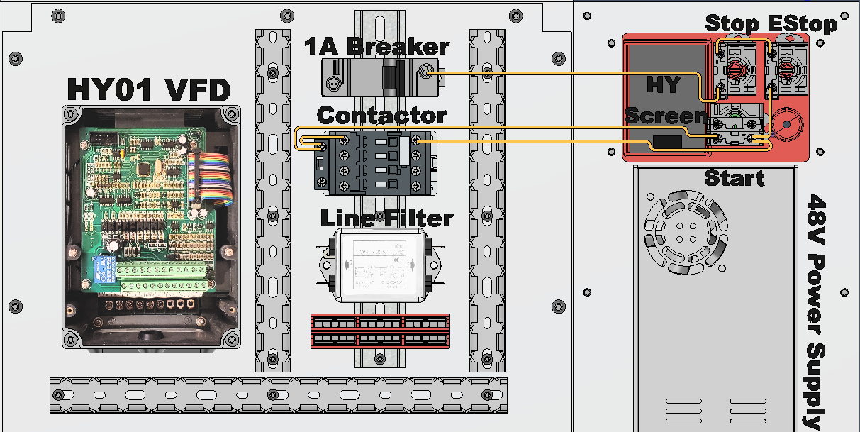
¶ Power Supplies AC Wiring
Ensure your power supplies are set to your incoming voltage (110/220 switch)
Use 1.5mm^2/16AWG stranded core hookup wires, with ferrules for power supply screw terminals, bare wire for wagos.
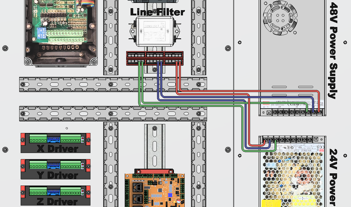
At this point - Test the function of the power supplies outputs, and use the trim pot to adjust the output from 48V down to 45V by turning counter clockwise. If you don't have a meter, just turn fully counterclockwise. For reason, go here:
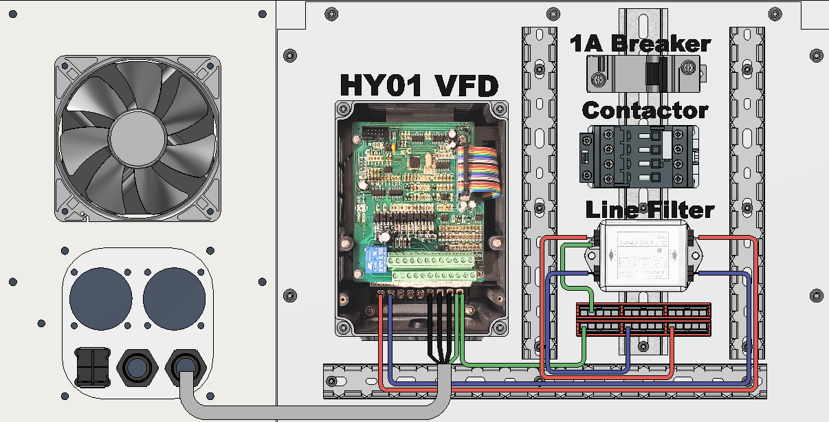
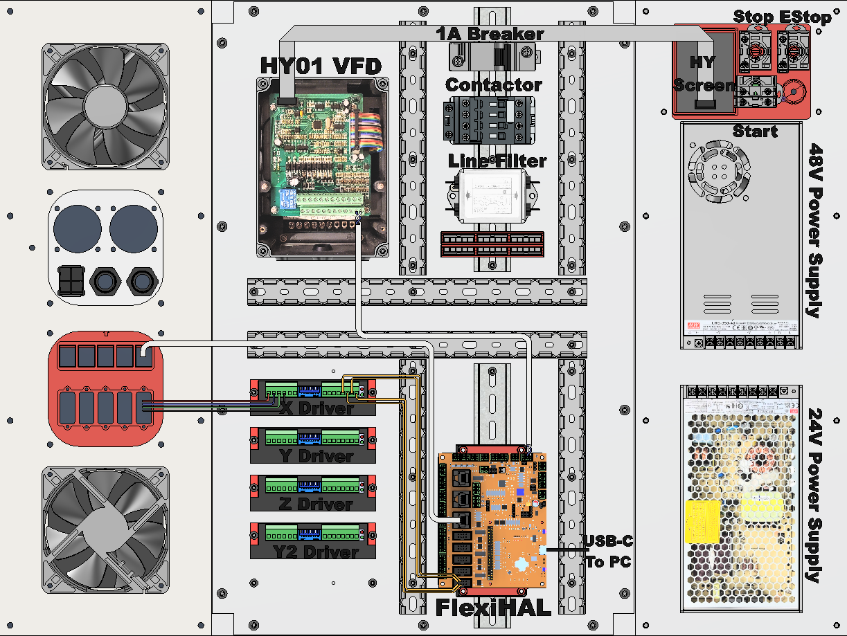
¶ VFD AC Wiring:
From wagos through line filter to VFD, then out to the spindle.
- Use 1.5mm2/16AWG stranded core hookup wires to connect the wagos to the Line Filter, using bare wire for wagos and insulated blue female spade connectors for the Line Filter.
- Use 1.5mm2/16AWG stranded core hookup wires to connect the output of the Line Filter to the VFD input, using insulated blue female spade connectors for the Line Filter, and ferrules for VFD screw terminals.
- Connect the Earth on the VFD to the Earth wago connector, using bare wire for the wago and a ferrule for the VFD screw terminal.
- Connect the cable from the Spindle to the U V W and Earth connectors on the VFD, using ferrules for the VFD screw terminals. The shield on the cable should also be terminated — for details on how to terminate the shield on the cable from the VFD to the Spindle see here.
Recommended: Install a ferrite core over the wires between the spindle and VFD with the jacket removed. Secure with zip ties. (more details here).
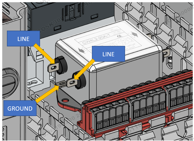
Pay careful attention to the Line side of the filter. There is a 3rd spade that the ground is connected to, as well as the two Line spades. The visual above is hard to tell, but the three wires go to three different spade connectors on the filter.
Tying any 2 of these wires together on the filter will result in a short.
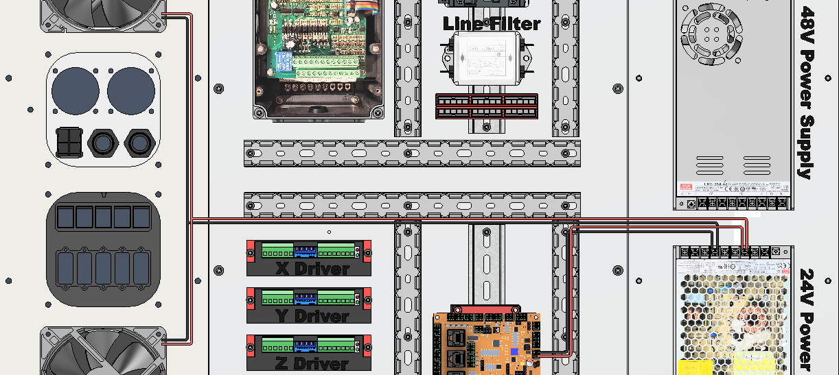
¶ AC Water Pump Wiring:
Important: Confirm your pump voltage before connection. DC24V, AC110V or AC220V. The pump doesn't always match the VFD voltage.
Easy mode - Connect the AC pump wires to the Red and Blue Wagos directly. If the contactor is on, the spindle water pump will be on.
More complex AC Pump wiring
- Connect a wire from the Red Wago to relay common on VFD (FB on HY, CM1 on YL)
- Connect a pump wire to NO on VFD (FA on HY, NO1 on YL)
- Connect other pump wire to Blue Wago.
- Set VFD to control pump with desired method - either on power on, or on spindle start.
- For HY VFDs, please follow this guide here.
¶ For DC pump, follow as above except instead of connecting to Red and Blue wago, connect to V+ and V- on 24V power supply.
¶ DC Wiring Section
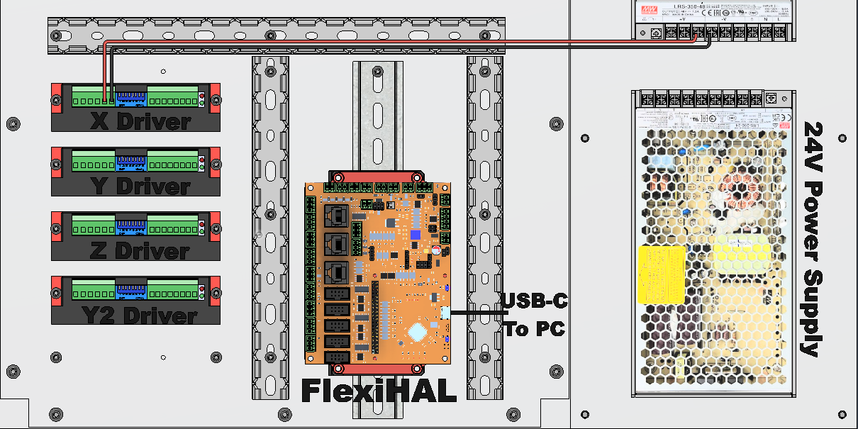
¶ 24V DC Wiring:
IMPORTANT: → DO NOT connect DC- jumper between power supplies. It doesn't provide any useful function and could possibly create an issue. Remove if it's installed.
Connect wires from power supply to FlexiHAL and Fan(s). Red is Positive(+) and Black is Negative (-) The upper fan should be mounted as an exhaust, and the lower as an intake.
Use 0.5mm^2/20AWG solid core hookup wires.
¶ 45V DC Wiring:
Wiring shown to a single driver. Connect red wire from Power Supply V+ to X Driver Vcc, and black wire from Power Supply V- to X Driver GND. Wire other drivers the same, directly from power supply to each driver.
Use 0.5mm^2/20AWG solid core hookup wires
¶ DC Control Wiring:
Use IDC cable from Flexi to Drivers. Strip about 10mm of IDC cable and fold the wires back over the jacket before crimping on the ferrule for better connection. Duplicate for the rest.
For individual wires - Connect X Step (S+/-) on Flexihal to Pulse (+/-) on X Driver. Connect X Direction (D+/-) to Dir (+/-) on X Driver. Repeat for other drivers.
OR: Use 4 wire dupont, de-pin and install in 4 pin socket. Ensure wiring and polarity is correct.
OR: Use Driver Keys. Details here: Driver Keys
Use extra length from your stepper to driver cable to connect between the optional screw cabinet disconnect screw terminals.
OR: Use cable passthroughs or cable glands and connect the stepper motors directly to the driver screw terminals.
Use twisted pair from Flexihal (A & B) to RS+/RS- on the VFD for RS485 (A to RS+ and B to RS-). Recommended: Add ferrite bead and/or rs485 isolator if having communication issues.
From VFD to Control Panel, use 5x2 IDC cable with 1 end rotated, or pull the socket off the display and rotate 180 degrees.
RJ45 ethernet cat5/6 from Flexihal endstop connector to sensor breakout pcb mounted on gantry.
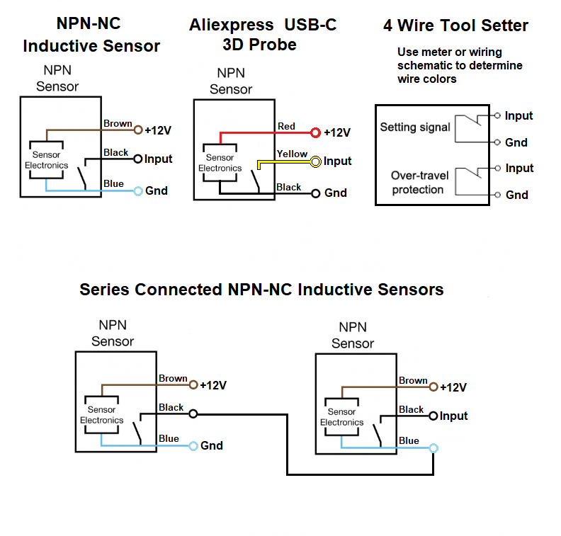
¶ Flexihal Pinout and Wiring:
Important: In the default configuration, Flexihal requires both the USB-C cable connected to the PC and the 24V DC power supply connected and powered on for the Flexihal to operate, due to signal isolation. The optional Jog2k pendant also requires the USB-C cable to be connected for power. There are jumpers on the controller to change the 5V source, check the github for details (recommended for advanced users only).
The A endstop and A stepper driver is used for Y2 on the printNC.
If you're connecting a toolsetter directly to the controller to save running the cable backwards through the Y cable chain, then use the Probe input (not the Tool) as there's a mislabel on the Flexihal A5. A7 has the correct label. For both it's connected as shown below.
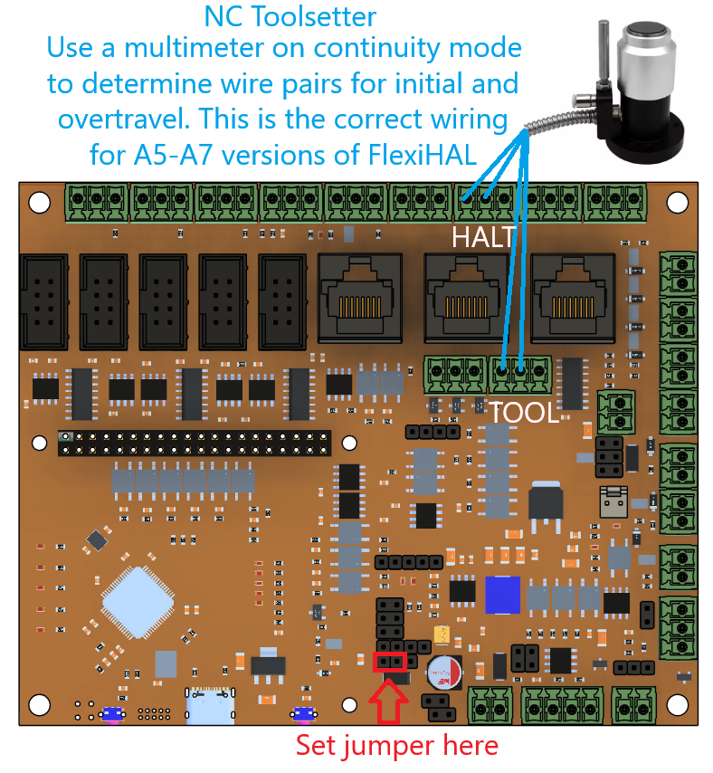
For use with Expatria's Sensor Breakout PCB, nothing additional is required. For use with Design by Logan's Gantry and Toolhead pcbs, the resistor pcb goes into the probe input and the toolsetter connects between Signal(S) and Ground(G)

¶ Stepper Driver Jumper Settings and Wiring:
¶ Stepper Driver to Motor wiring:
A+/A- connects to one coil of the stepper motor and B+/B- connects to the other coil. Wiring guides included with steppers are often not accurate, so it's best to test the stepper coil pairs -
either by connecting 2 wires together and trying to turn the stepper (a closed loop connected to a coil will make the stepper harder to turn) or a multimeter on continuity (ohms) setting.
Polarity of the connection doesn't matter. Just check the direction of the motor rotation and if it doesn't match the intended rotation, swap two wires at the driver (typically A+/A- are red/blue, but wiring varies by stepper so test instead of assuming it's correct)
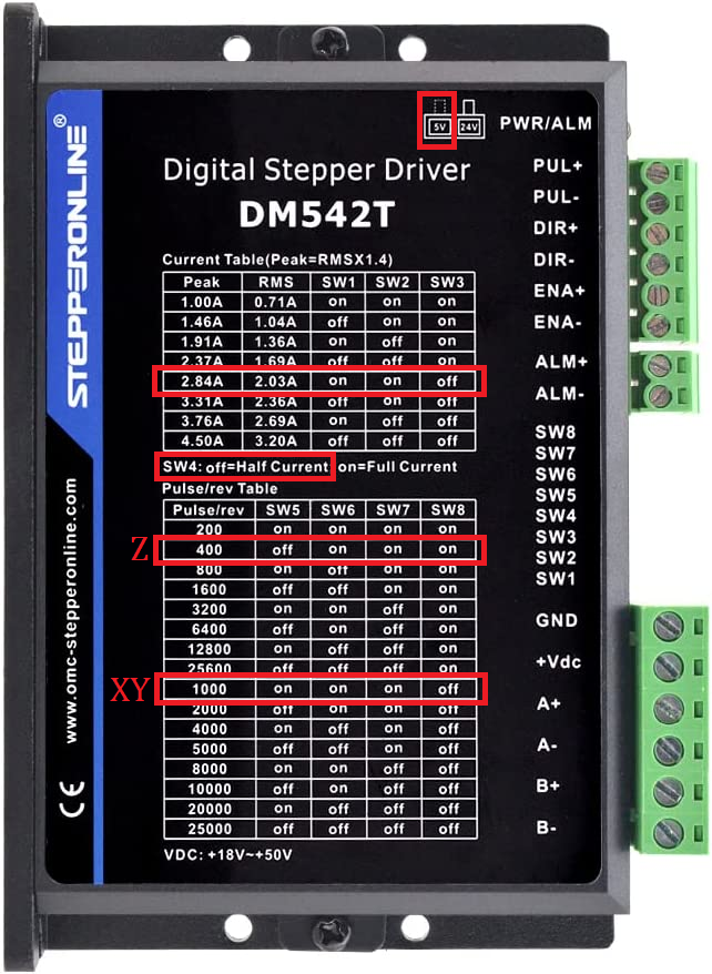
¶ Stepper Driver Switch Settings:
The following settings are for the stock 3.0A steppers included with the kit and PETg printed mounts. If you have metal motor mounts you can increase the current a bit but watch for skipped steps and overheating.
XY is set differently than Z because the ballscrews are 10mm per rotation for XY and 4mm per rotation for Z. In Grblhal set 100 steps per mm for all axis.
A switch is ON when pushed down/towards the back of the driver. Switch 4 for half current is when driver is idle, less current is used to allow the steppers to stay cooler when not moving.
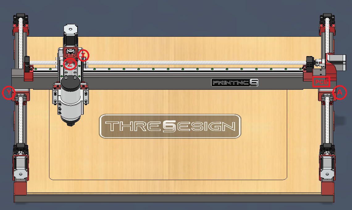
¶ Wiring from Electronics Cabinet to PrintNC
The following wire runs are used in the PrintNC from Electronics Enclosure to PrintNC frame, using the estimated lengths from https://wiki.printnc.info/en/v3/wiring#wires
- X Driver from Enclosure through Y cable chain to stepper end of gantry.
- Y (Y1) Driver from Enclosure through Y frame to Y1 stepper. Note: if enclosure is on right side of cabinet, switch Y1 and Y2 cable lengths.
- A (Y2) Driver from Enclosure through rear X frame and Y frame to Y2 Stepper.
- Z Driver from Enclosure through Y cable chain and X cable chain to Z Stepper
- VFD from Enclosure through Y cable chain and X cable chain to Spindle.
- Endstop Sensor Cat5/6 cable from Flexihal (or equivalent controller) through Y cable chain to Endstop Breakout PCB on Gantry. (Optional: Cat5/6 cable from Gantry PCB to Z axis Toolhead PCB through X cable chain.)
- X Endstop sensor cable from Endstop Breakout PCB through X cable chain to X roller. (optional: connect to Toolhead PCB)
- Y (Y1) Endstop sensor cable from Endstop Breakout PCB to Y roller.
- A (Y2) Endstop sensor cable from Endstop Breakout PCB through X gantry to opposite Y roller.
- Z Endstop sensor cable from Endstop Breakout PCB through X cable chain to Z Stepper mount. (optional: connect to Toolhead PCB)
- Toolsetter cable from Probe Input Sig + GND on Flexihal (or equivalent controller) to Toolsetter location on wasteboard.
¶ Sensor locations and wiring colors: