¶ Why adjust the 48V power supply to 45V?
The manual for the DM542T Driver states that 50V is max voltage including back EMF generated by the steppers' motion and that 10% overhead should be provided to reduce likelihood of damage.
50V - 10% (5V) = 45V.
¶ Stepper and VFD/Spindle Shield termination.
The VFD to Spindle cable is a special case for shield termination, as it must be connected to the ground point at both ends of the cable to prevent electromagnetic interference (EMI) from negatively affecting the VFD, Spindle and other components.
Wire 4 wires from P1, P2, P3 and GND respectively to U, V, W and E on the spindle. Use a double shielded (foil+braid) VFD cable for this connection, as you don't want interferences for that connectivity.
Best method: Run the VFD cable continuous from VFD directly to spindle without any connectors between. Use a split plate and rubber grommet or cable gland for entry into the enclosure. Terminate the shield at the ground screw or dedicated shield screw on the VFD (if available)
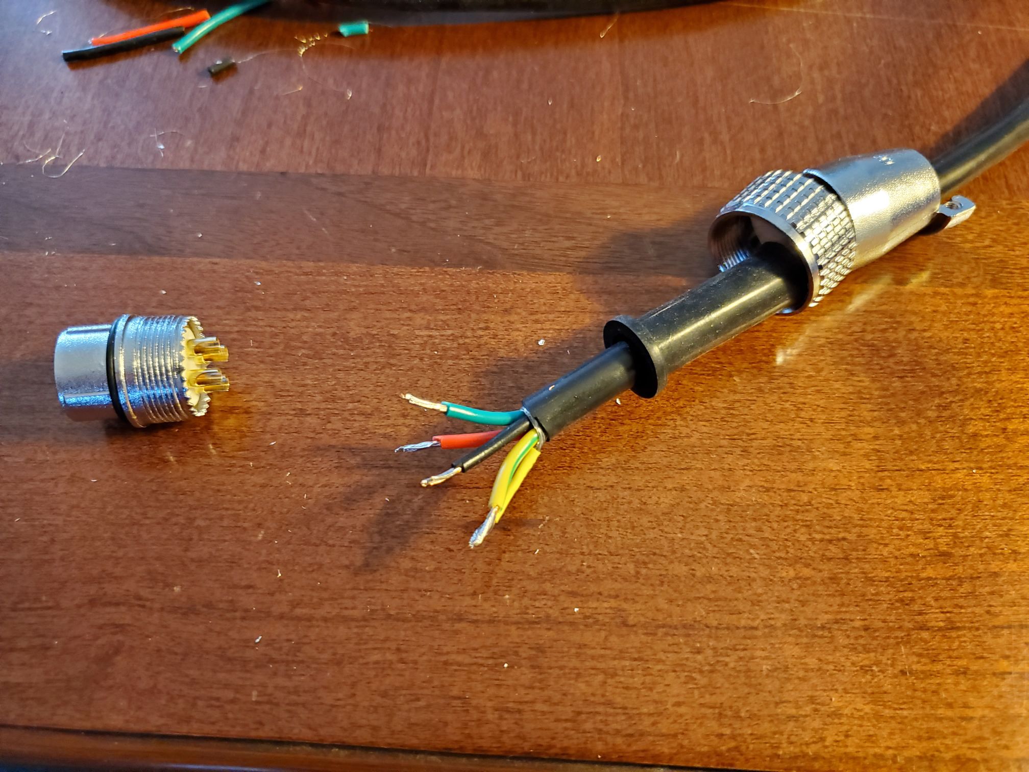
If you require a midpoint disconnection means, isolate the shield from the enclosure and connector by twisting into a wire and using shrink wrap, and connect to a separate pin from the ground wire to maintain the shield over the full length of the wire. The shield needs to continue from enclosure to VFD.
Twist the braid shield into a strand and use a bit of heat shrink to keep it together, then solder to pin 4 with the ground wire.

See the Belden Inc. video demonstrating how to terminate foil/braid shielded VFD cable directly to the VFD:
Belden Inc.
For more information about why shielding is important:
Belden - Tips for Properly Terminating VFD Cable
¶ Ferrite core around VFD wires
The VFD wires go from the wago connectors, through line filter to the VFD, and then out to spindle. It's recommended to install a ferrite core over the wires with the jacket removed, with this secured with zip ties. Only the AC lines need to pass though, with the ground and shield kept outside (discussed here).
