¶ Assembly Guides
Current build guide matching the newest fusion model
Build guide for V1 CNC. Some instructions are no longer valid for V2.x. Doesn't cover Z-axis.
Video build walkthrough, narrated by PrintNC designer Hoges. Some instructions are no longer valid for V2.x.
Untested unreviewed in-progress v3.0 Z-Axis Assembly Instructions
Electronics Wiring and LinuxCNC setup
Making the Z-Axis
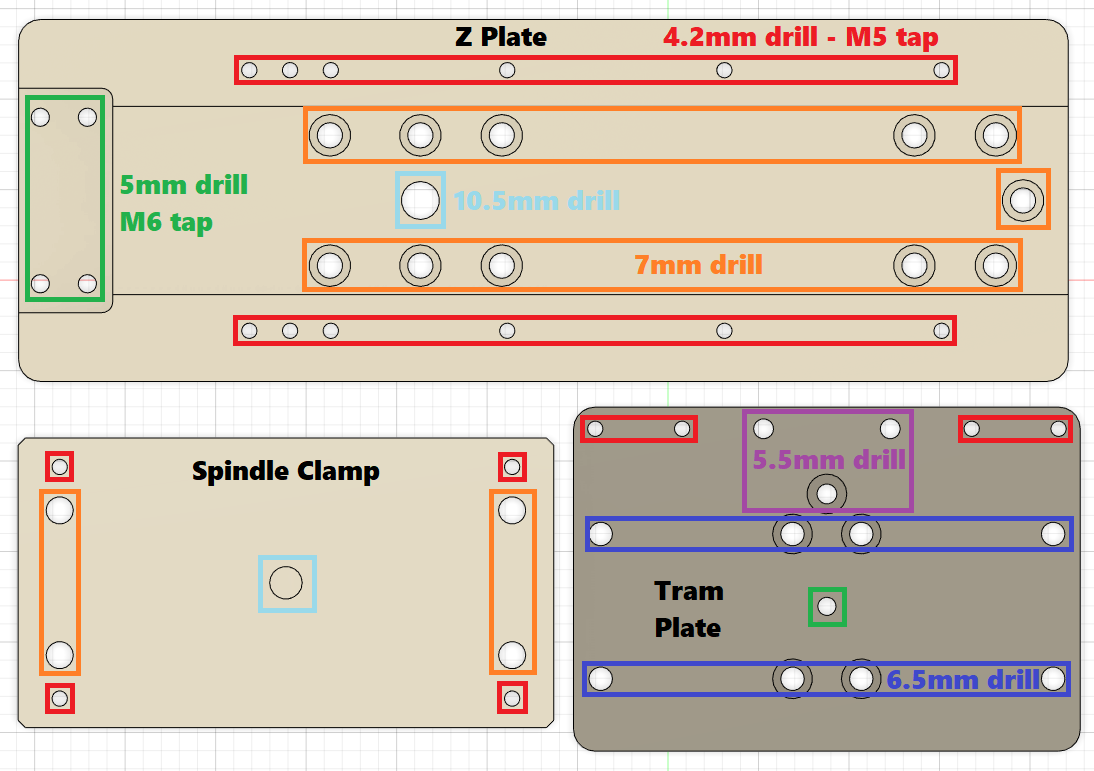
The Z-assembly is generally made from aluminum. there are a few ways you can have your plates made.
- Make them yourself
- Machine in aluminum/wood with your own CNC (e.g. MPCNC)
- Handcraft aluminum plates using woodworking tools (aluminum can be machined easily using woodworking tools)
- Handcraft plywood plates (minimum 12mm) to get your machine running, then machine them on your new printnc
- Have them made for you
- ask the Discord #marketplace to see if anyone will make them for you
- ask local machine shops
- utilize Aliexpress or a similar service
- [currently unavailable 2020/12/04] Buy them from the ThreeDesign store (made by Hoges)
- See the FAQ below for further ideas on how to get started with your Z axis build.
¶ Frequently Asked Question - PrintNC Assembly
¶ Q - Can't find the assembly tools in the new fusion assemblies, I mean I found some of the assembly tools but not all of them?
Stanley: I’ve noticed the same thing, I can’t find the models for the tools used to mark up the hole locations. Does anyone have the models for these?
ldc79: I have found those in the 2.0 fusion assembly
Logan: The Z assembly tools are in the narrow Z mod file.
ldc79: Sure, I was looking for the 6A tool
Logan: Yeah, the tools are usually the last thing to be made after the design is completed. But the v2cnc file should have all the assembly parts for X and Y
ldc79: sure that's where I have found the 6A
¶ Q - Is there an quantity list of plastic parts anywhere?
The quantities are in the fusion file really, I'm not sure there's a separate list. It also varies by build size
¶ Q – What is the rough order of operations and game plan for a build for an inexperience user?
[Note: This is just the thoughts of one community member, timelines are very situational and many members were up and running in the weeks to two months range.]
Beef: depending how quick you want to get the machine up and running, and how much knowledge you have (I see you already put together a mpnc), you can figure out what your plan is - for me (who's hasn't put together a cnc machine before) its:
1. figure out work dimensions
2. play around with different steel sizes and beam deflection calculators etc. to figure out what I want to run
3. think about what "additional" capabilities I will want to run (4th axis, ATC, multiple spindles, whatever) since even if they're not something I'll run even for 12-18 months, they may have impacts on my frame or footprint decisions
4. order steel
4b - build a workbench to fit it on top of because my dimensions are bigger than anything I have currently
5. mock up frame and verify dimensioning
6. make aliexpress order for "electrics" (motor, bearings, rails, etc)
7. drill / tap / paint / assemble frame
8. receive ali-express order and assemble mechanics / motors
9. research the control mechanics and electronics, and put together order for electronic stuff
10. wire it up and let it ripbut you have more familiarity with the electrics / electronics / mechanics of cnc setups, so you can probably combine steps where I am purposely taking baby steps so that I can wrap my head around it as I go, instead of trying to drink from the fire-hose of everything at once before I make an order
my timeline to have a working machine is long as well - 3-4 months until my first cut is acceptable for me
¶ Q - I am just worried that no matter how or who cuts the box steel, when using the edge for the template, there will be errors with alignment? Like how exact does it need to be?
Logan: The only edge that really matters is the side of the rollers the ballscrew attaches to.
hoges: good but not perfect, the tools and rollers are designed to accommodate non perfect cutting
¶ Q – How precise do the cuts and setup need to be? I’m concerned I won’t be accurate enough.
@hoges: remember the design intent of the entire machine is that it can be made with basic tools. I cut my original machine using a angle grinder and electrical tape as marking. just rough cut then ground it down to as close to square as possible. pretty much any cut will be better than that
¶ Q - I'm optimistic that I can carefully unbolt and mark the frame when I have to move and take the PrintNC out in pieces and easily bolt it back up, is that reasonable?
@logan: Yes, that should be feasible. To make this easier, I have hash marks on the X frame pieces on the left side, 1 for front, 2 for middle and 3 for back. Easy to realign that way. Used the angle grinder to make them in the edge.
¶ Q – Are there any hand held drill press options designed for steel?
If you haven't worked with steel before, it can be intimidating. Many members have had good luck using a hand drill, tapping fluid, pilot holes and patience to drill their steel. Then they come back with a combo drill and tap bit and use the previous pilot for alignment and tap the holes.
If you have a drill press, the drilling can easily be done on the drill press and a fence can be used for alignment if desired. A roller can support the loose end of the steel. Always wear eye protection and use safe workholding methods.
If you have access to tool rental options, or a friend who works with steel, there are special tools optimized for working with steel. These ARE NOT necessary to build a PrintNC but if you happen to have one available may speed up the steel drilling portion.
There are multiple products from Milwuakee that may be available for rent from your local pro tools store. One model is https://www.milwaukeetool.ca/Products/Power-Tools/Drilling/Magnetic-Drills/4270-21
Note: Mark Hoges, the creator of the PrintNC, does all of his drilling and tapping with a regular cordless drill. His advice is to make sure you have fully charged batteries, use tapping fluid and be patient. A handheld drill press/guide for the drill is optional to aid in squaring up to the steel but is not required.
¶ Q - I don't have any drill bits for steel / metal, can you recommend some? Any tips for using them?
@ballen I was really happy with these: https://www.ebay.com/itm/21-Piece-Black-Oxide-Finish-Steel-Metric-Drill-Bit-Set-for-Metal-Wood-Plastic-/372153036231
ldc79: The cheap amazon stuff. I couldn't find good ones so I got two packs
Trader: That was my plan. Did the second one hold up any better? :slight_smile:
ldc: I only snapped one but it was inexperience. Go low speed, Low torque. And when it gets stuck just reverse direction and lubricate. And repeat. But it is very easy. Also hold very tight your drill as it tends to tilt otherwise. It is actually very easy. Drilling holes in the steel is surprisingly easy with good drill bits. I have quality bosch drill bits and they are very sharp.
¶ Q – Any general purpose tool/supply companies I should be aware of? Where can I get metric fasteners?
Tools, Hardware, General Workshop: Harbour Freight (US) / Princess Auto (Canada)
Metric Fasteners: McMaster-Carr, Fastenal, Grainger
Electronics and connectors: DigiKey, Mouser
¶ Q – How do you clean the steel to prep it for painting?
@evanlane: I know others have already responded, but you can also leave them in a white vinegar bath overnight and then wipe them down. It helps remove all the mill scale and rust easily. I don't think acetone really does the job for that. It's probably not functionally necessary. I think mill scale is only around .1 - .2 mm thick so it shouldn't affect much. Makes it damn easy to get paint to stick though.
What did you use for the bath frame? I use an old long cardboard box I lined with some thick gardening plastic. I think it was initially a florescent light cardboard box.
Do you use a 50/50 water mix? I don't, but I think you could. I got a buddy of mine to buy a couple 5 gallon things of vinegar from a restaurant supply store, so it wasn't too expensive.
Don't forget to either turn the stock in the bath or prop it up on a couple small plastic bits, so the vinegar gets to all sides.
--
Trader: @DZwijnenburg Did you use a spray can paint or a brush on paint on your steel?
DZwijnenburg: I used an old fashioned roller
Trader: How did you prep it? (the steel)
DZwijnenburg: I grinded it with 120 - 180 grit, then handsanded with 240, then cleaned it with this one: https://www.verf.nl/artikel/3449/universol-verfreiniger-ammoniakvervanger.html and then the first layer with this paint: https://www.verf.nl/artikel/3223/brantho-korrux-3-in-1.html and I think tomorrow I'll do a second coat
than maybe in the weekend I can drill and tap some holes
--
WhichWayWazzit: Used a drill. Used 1/8" as pilot hole first
Painting prep was a quick sand with 120grit, wiped down with degreasers
Then rust-oleum spray paint, two coats. Close to two 12oz cans 0n a standard size build.
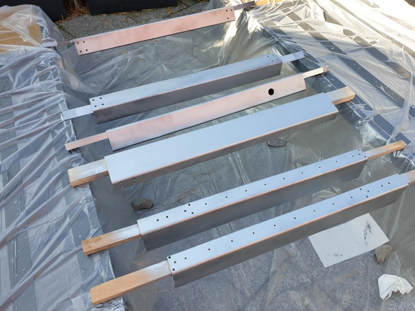
¶ Q – Any suggestions on how to support the steel beams to paint them on all four sides and for drying?
Yes, run some 1x3 or other lumber through to and hand them between saw horses like in this photo:
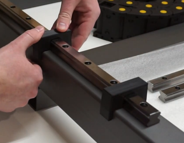
¶ Q - I see people use these centering helpers for the rails, but I don't see them in the fusion file. Where do people get that?
Redux_Hz: those are under the mods section of the wiki
Cybran Nakh: Those guides are SO useful
¶ Q - Are there any other highly recommended upgrades/updates for the printed parts?
Yes, see this page: https://wiki.printnc.info/en/project-files
¶ Q - How is the waste board secured to the frame?
Most people drill and tap bolt holes in to the X support members and use bolts with large washers to hold down the wasteboard.
@Logan pointed out that technically the first layer is the base board and the wasteboard sits on top of that.
NOTE: Confirm that the X support beam section of the assembly guide has the step for adding the wasteboard holes, will be easier to do on the drill press.
¶ Q - People often refer to using double sided carpet tape around the shop (and in one step of the assembly). I've never bought it before. What am I looking for and do you pick it up at home depot?
Logan: Sure any hardware store
Rcw: For the 6A drill guide, literally any double-sided tape will work. It just needs to stay put for a while. For workholding, I think there's a preference for thinness, so it can't wiggle as much. (I personally just use painter's tape + superglue for workholding - and, actually... that'd work for 6A as well)
¶ Q - Anyone know why the there are 2 #6 assembly tools for the X-gantry? There's a #6 and #6a. The assembly guide doesn't mention anything about a 6a - shouldn't the regular #6 work for both sides of the gantry?
@logan: You use the 6 to do one end, then place the other one centered on the roller with double sided tape facing up, then with at least 2 bolts installed from the 6 end, drop the gantry onto the roller with 6a. It'll stick to the gantry, flip it over and drill the holes.
this ensures the holes are the correct distance apart.
And you won't have to oval the holes by wiggling the drill back and forth like I did.
aethyr: ah I see, in case the x-gantry length is slightly off?
Logan BC: yep. make sure your frame is square and parallel before this step though.
¶ Q – What is the optimal order of operations for completing the Z axis/Gantry assembly?
[Please refer primarily to the full assembly guide - even though it is a little bit out of date it is very thorough up to the Z axis assembly. This area needs more work but capturing what we have for now]
Logan: It also is much easier to install the carriages on the rails first, then the plate to the rollers. Same with the rollers for Y. I would drill the holes for the gantry to rollers before installing the rails. The order you drill the holes doesn't really matter though. And your motor mount can't be installed before you attach the gantry to the rollers.
Basically. use assembly guide 6 to drill the holes on one end of the gantry, then place 6A on the roller at the other end with double sided tape on top. align the 6 side with the holes in the roller, press the gantry down on the tape, and then flip it over and drill.
¶ Q - Is there a recommended time during the assembly to apply the grease to the carriages? I see that it can be difficult to reach the grease fittings once the Z is assembled, for example.
Joeyp: You cant grease the carriages when they are off the machine, do it once the rails are in their final position but before you bolt anything to them that would make it hard to do.
Logan: I installed slots in my X rollers so the fittings are accessable.
Trader: Does the timing of the grease matter? I would prefer to do it when they are off the machine.
Logan: you have to periodically regrease them. so making it accessible instead of disassembling 1/2 the machine is the best option.
Trader: I don't think I saved the photo, can't remember exactly what you did?
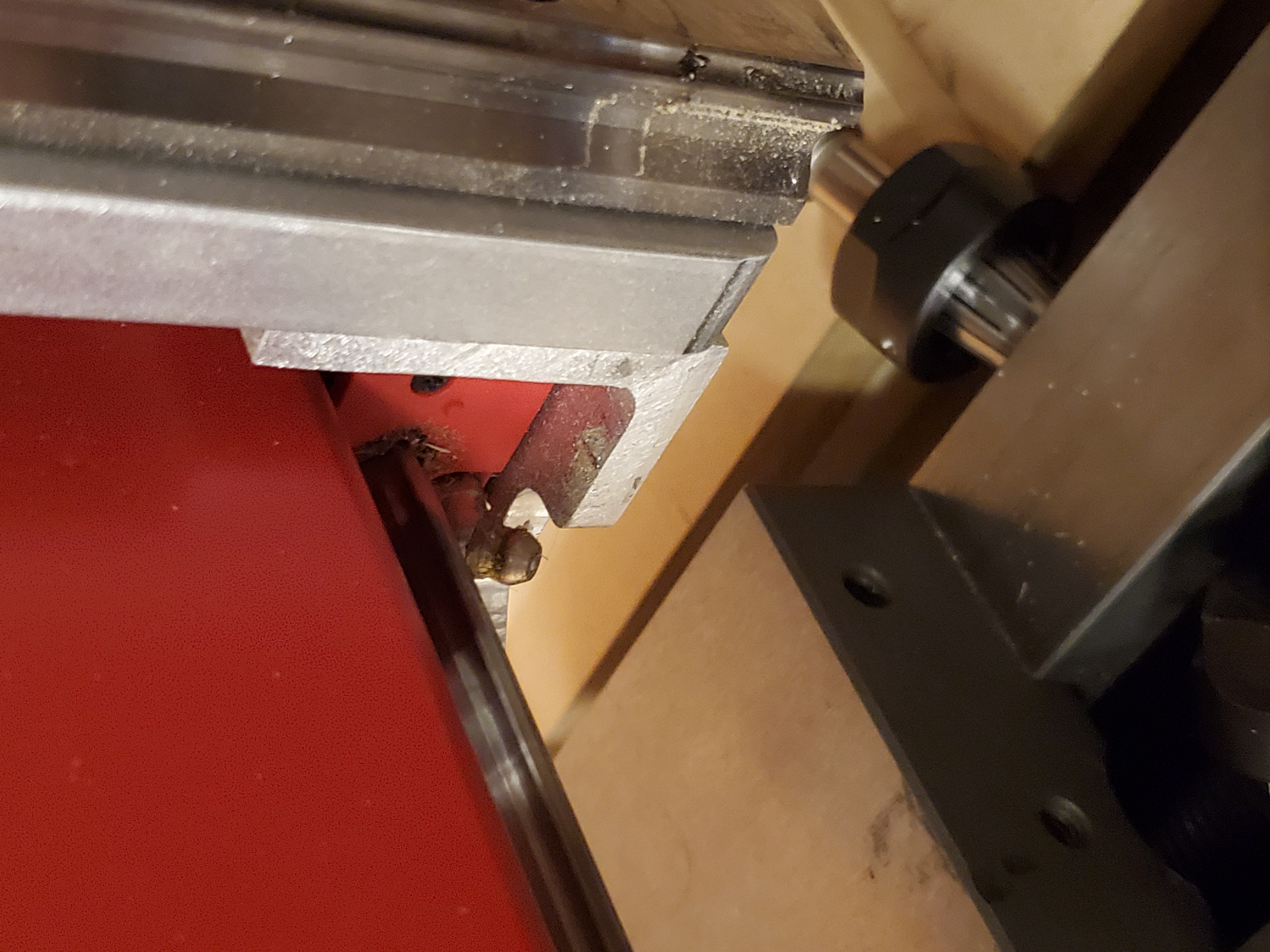
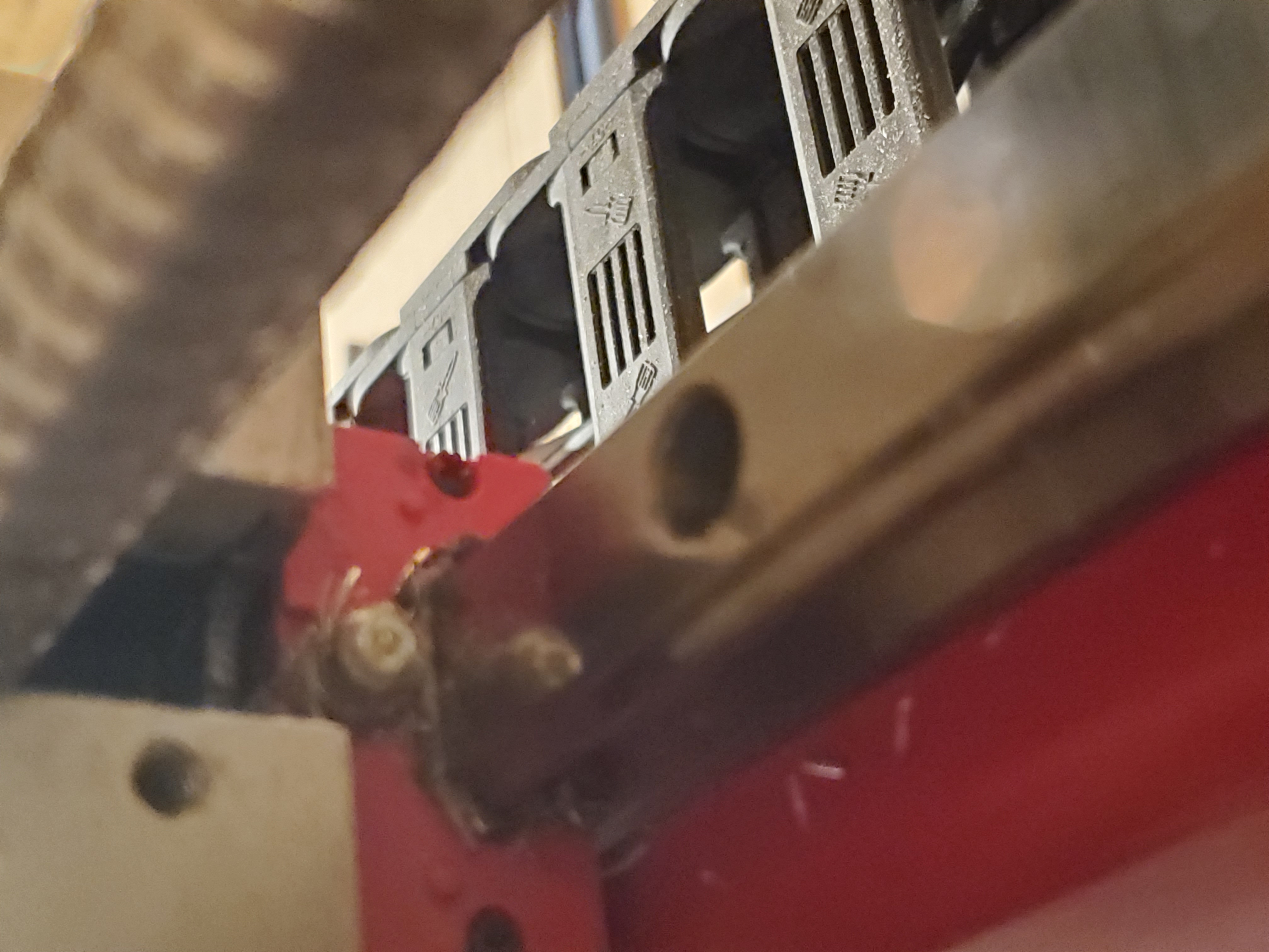
Trader: So mill the angle aluminum before installing it? Any chance those notches are in the model?
Logan: lol nope. Depends which side your angle is facing. A zerk extension would also work.
Trader: Ok but notching both sides of both pieces would eliminate that consideration? both ends of both pieces, rather
Logan: true, but if you don't have a working machine, milling notches is tougher.
Instead, drill a 1/2" hole and saw out the piece works for both though.
Trader: Good pt. Or if still building, do that as part of assembly
¶ Q - Is there a standard form factor for grease cartridges?
Logan: yeah, regular and mini. mini is 3oz, regular is like 18 I think?
thesnuggs: 14 maybe? 14oz plenty for the initial fill?
Logan: 3oz was enough for my whole machine, so yeah. I need a refill for top ups later though.
¶ Q - I got the grease gun but can't get it really working. When watching videos it's all very simple
ldc79: Attaching to the zerk is next to impossible
Logan: loosen off the collar by unscrewing it. it should just easily slide onto the zerk once loose enough, then tighten, then pump the gun. 1 pump is usually enough, then loosen until it easy slides off again.
¶ Q - Anyone else have the ball bearings come out of their carriages when handling them? The balls are held in place by very delicate plastic. I'm surprised I'm on the only one that's had the bearings pop out.
hoges: you're not... you should never take the carriages off without an insert in them. You push the insert out with the rail when you're sliding it on I've learnt the hard way about being delicate with this too
I have a few carriages with missing balls, it's not a big deal they are still fine to use
Logan: think of them like little marbles
aethyr: ah...that makes sense for the inserts. I just immediately took them off and tossed them in the trash lol
Logan: you can print new ones
PRO TIP from banchad: Once you’ve finished building don’t throw away the bearing retainers for the linear rail blocks in case you ever have to remove them from the rail! Dropped my balls all over the garage
¶ Q - If you already have a smaller CNC, what (otherwise) printed parts can and should be cut from AL from the outset?
Xenobe: ballscrew faceplates
@hoges: keyhole ballscrew plates are standard now and i am just finishing off the millable keyhole plates with little covers for people like me who open keyholes would drive insane
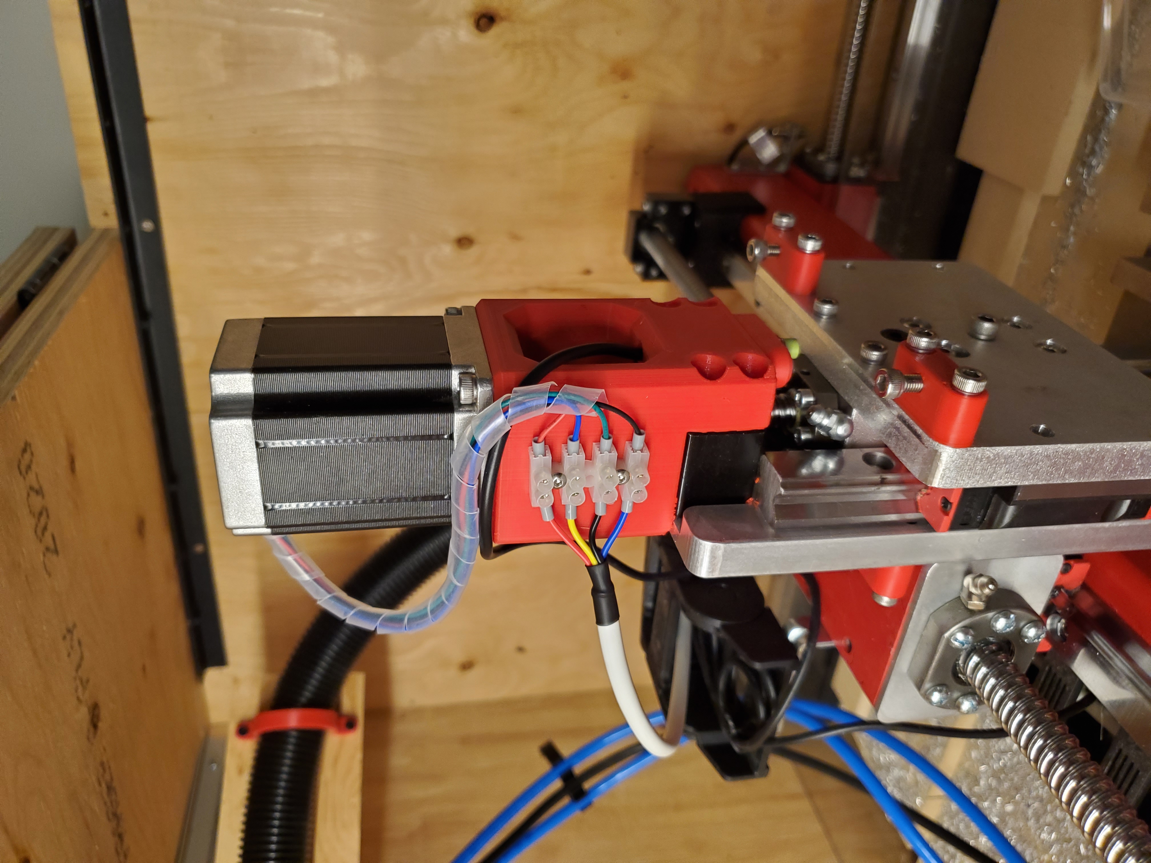
¶ Q - For the stepper motors, how do you connect the little wires from the motor to the larger wires going back to the drivers? Seems like the moving axises would be subject to strain there?
kotlikm: I used these: https://www.amazon.com/dp/B07NPR2HX1/ref=cm_sw_r_cp_apa_fabc_wsddGbREX9DJ3
kotlikm: M3 bolts work with those ones.
thesnuggs: So terminal block moving with the axis?
kotlikm: Tapped holes in the steel to mount them.
Logan:
¶ Q - Is there an option for another plate under the spindle clamp? Needed for the narrower clamp that I have
irrenhaus : There is a parameter that enables a second tram plate, just like in the original design, if that is what you mean. My bad, I think it's not actually a parameter but simply a hidden part
¶ Q - Is there a reason why the angle bracket in the narrow-Z is 1/4" aluminum and not say, 1/8" steel? My metal supplier didn't carry 2x3 angle in aluminum, so I tried welding 2 flat Al pieces...and I failed miserably. So now thinking of just making the angle out of 1/8" steel?
@hoges: Steel would be fine. You can even cut open a roller into 2 sections if needed.
¶ Q - Is there a guide for building the Z axis plates on youtube or wiki? It would really help with making these parts?
ReduX_Hz: (aka Projects by Brian on YouTube) I made a video on it that might help, however it was more focused on assembling the z axis rather than building the plates themselves
¶ Q - So I see a lot of aluminum Z plates - any reason aluminum vs steel?
GTKpluplus: Easier to machine on a printNC. Also, I have steel plates, I think I hurt my back lining up the Z axis to the X axis - that thing is heavy.
¶ Q – I need to use a handsaw to cut some of my aluminum and wooden parts for my temporary Z. How can I get straight cuts with a hand saw?
There is a lady on YouTube who goes by "See Jane Drill". I think the presenters name is Leah Bolden. She really knows her stuff but offers amazing 5 minute tips on simple and complex things. She teaches construction I believe. She did a video on handsaw technique and had a very simple tip. When cutting with a handsaw, point your index finger along the saw blade while cutting. It causes you to make very straight cuts. Totally works.
She also mentioned that table salt makes a great hand cleaner at the end of the day, works great.
Cybran Nakh: I saw a guy give similar advice. Also holding the saw on both ends helps with stability and accuracy
¶ Q - What is the suggested/easiest z axis to make by hand? I am quite lost due to the lack of documentation on the new Z axis.
gerrg: I would print out a drawing of the plates on paper and glue them to a piece of wood. Then drill all your holes. you can make the step down for the BF mount either with a piece of wood behind your long plate, or make your plate thicker and use a router to cut out that section to the proper depth
https://discord.com/channels/648972213734604807/741009871859875850/798233456768319500
¶ Q - Is anyone building a z-axis from wood? What about the angle pieces?
Yes, lots of people, including Logan who designed the V2.1 aka Narrow Z assembly cut their first iteration from wood. Once the machine was up and running then they used the machine to mill their final aluminum version. It can be cut by hand or on another CNC out of wood to start.
For the angle pieces, they can be purchased at your local metal supplier or most home centers. If aluminum, they can be cut with a jig saw or on a chop saw but always sandwich the material between wood and fully clamp it before cutting. If unsure how to do It safely, do more research first.
@hoges: Z Axis has been broken into 2 distinct components - Milled Z (essentially identical to narrow Z mod) and a second simplified Z which has no pockets and designed for DIY from wood with basic tools. the simplified version does not have any tramming features as it's intended as a interim measure
¶ Q – How thick should the plywood be for the temporary wooden Z plate?
Logan: My 3/8" ply Z and tram plates worked for milling my aluminum ones. 1.2mm stepover and 3mm doc, 18000 rpm and 1500mm/sec feed, I think? Something like that
ldc79: 3/8?? So thin? Wow
hoges: the simplified plate doesn't have any tramming options. It's purely intended as a stop gap to get a machine running that will allow you to cut your own plates. The larger tramming plates that Logan has design conflict as you have seen. The way I intend for this to work is you make the smaller original plate which doesn't rise this high with the same wood as you made the faceplate with
Once the machine is running you and you're making the metal version the spindle plate needs a small 1mm pocket where that interference is
ldc79: If I decide to start with a wooden Z going to aluminum is just a matter of mounting the new face plate? And tramming? The rest should work?
hoges: that's right, the wooden faceplate just removes all the extra bits so it as easy to make as possible. The bolt patterns and mount are all the same, it's just a matter of unscrewing the wood one then bolting on the metal one once they're done
Logan: You still need to use a forstner bit to countersink the screws don't you? Or does your printed part and the rollers have enough clearance for the buttonhead screws? I thought there was a conflict there still as well.
ldc79: No problem to countersink
¶ Q – Someone said the Z plate is frame size dependent, why and what is the ratio/relationship? Is there a way to standardize this so it can be produced in volume?
hoges: It will vary depending on the steel section. We know enough about what is commonly available around the different build regions to offer a few standard sizes. I'll chat to @yanli xing and see what can be arranged
The common sizes are 3x2, 75x50, 80x50, 4x2 and 100,50
The plan is to make 75x50, 3x2 and 80x50 all work off the one standard plate.
¶ Q - I noticed the current Narrow Z plate is 12mm thick. Can this be made out of 12.7mm Birch as a temporary build? What about the other two plates, one being optional? I actually see the front plate for the spindle is 15mm. I'm guessing .5" Birch ply is fine on all three plates?
hoges: yes thats fine, the plate thickness is not critical. If you're building out of wood then thicker is preferable. the front plate where the spindle mounts is just to provide clearance over the Z mount, just acts as a buffer plate. On the metal version it also allows tramming but tramming is not considered needed for the temporary wood parts
¶ Q - I’m a bit confused regarding the X roller and X angle pieces. The frame calculator says that the X roller should be 100mm (it says nothing about the X angle, but I assume it’s the same length as the roller), but in the cad drawing they are both 135mm long. Which is correct?
hoges: The narrow Z mod has been adopted as the official Z axis. This uses 100mm pieces on both top and bottom
You can use the newest Fusion file that is very close to finished but still lacking a handful of assembly tools and a little bit of testing
This file is much faster to work with compared to the old and contains all the mods
The parameters operate differently as all files parameters are set using the base parameters file which will then reflect across all files. The individual component parameters are no longer adjustable individually from within the file
¶ Q - Is this the correct way to install the BK block on the Z assembly?
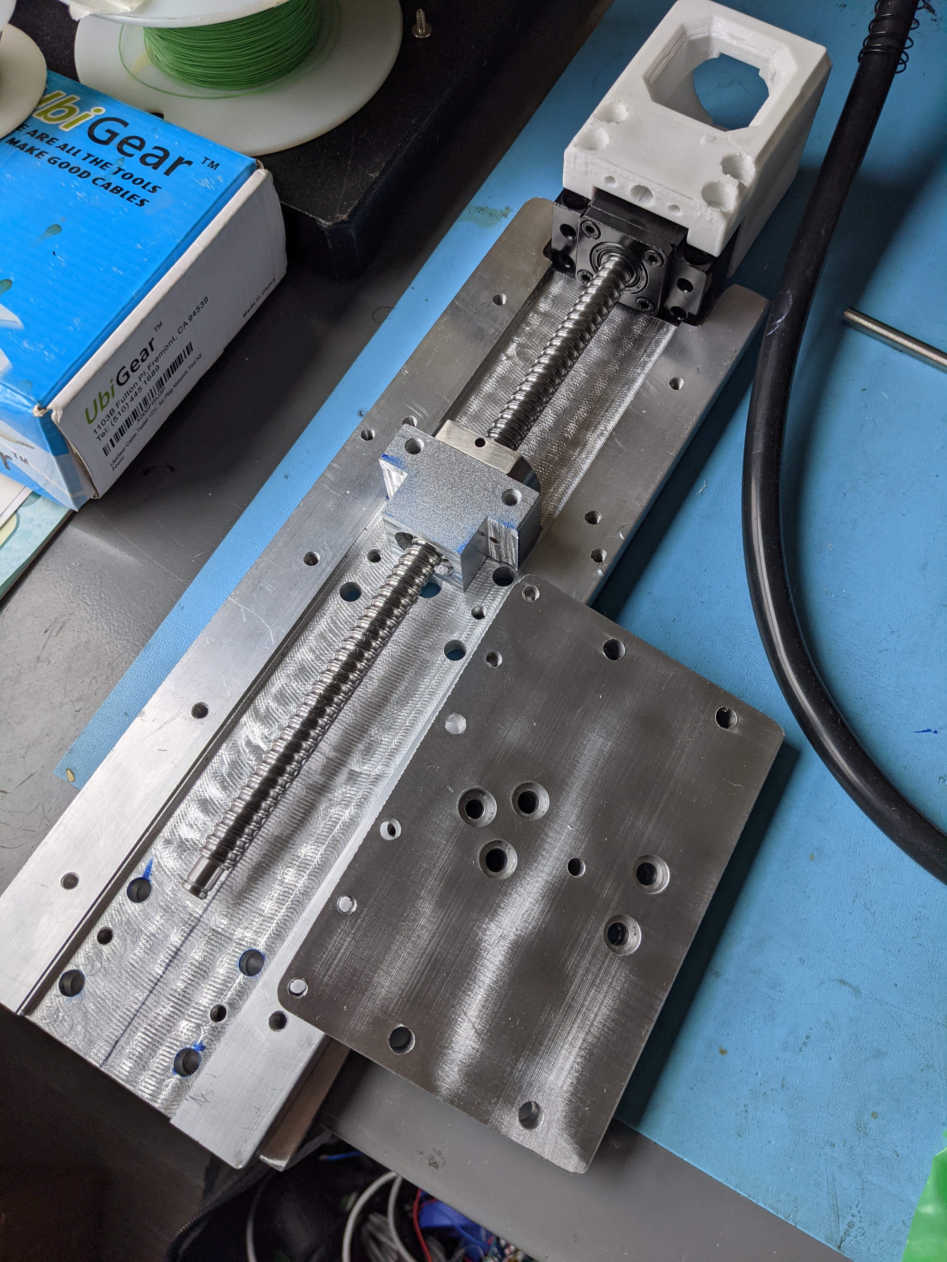
Logan: No, this is backwards. Your BK10 is reversed, should have the bearing plate facing up.
¶ Q – I have been so confused as what grease to use for the bearings. Some say Super Lube and others say super thin oil. Which is it?
I have this in a grease gun
https://www.amazon.com/gp/product/B000ILHVQ2/ref=ppx_yo_dt_b_asin_title_o06_s01?ie=UTF8&psc=1
multipurpose no-additive grease. can be super cheap. brown grease is what is recommended by hiwin but i doubt white hurts **forgot to mention should be lithium
my intuition says PTFE wont hurt. what they mention is that you dont want molybdenum disulphide particles, graphite particles, etc..
i cant say for certain though.. not my area of expertise
i just read the manual lol
https://discord.com/channels/648972213734604807/648972213734604810/797343508414988288
Ok NLGI 2 is what Super Lube is
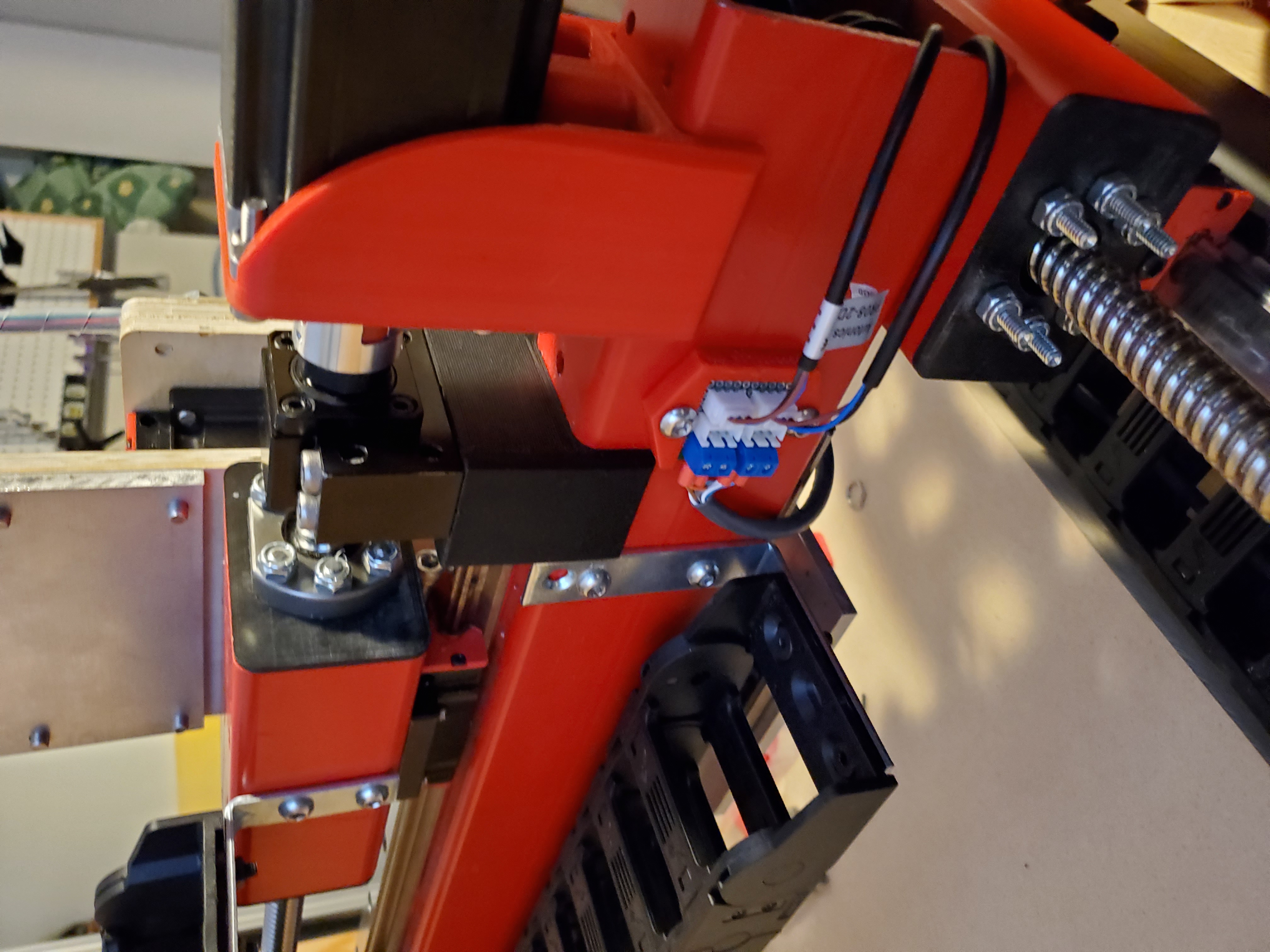
¶ Q - Can someone show me how to mount the drag chain?
@logan just used a simple piece of angle bracket. Which works well if you didn’t plan on the extra 3” extension to your X grantry beam:
¶ Q – How do I square the machine?
The short version is you make an isosceles triangle, or try to. I use the left side of the frame so you can start at X0, drill two holes in a scrap board and into the wasteboard at least 100mm apart on Y.
Jog to the midpoint of the two holes (50Y) and to 1/2 the distance between the Y motors, drill a 3rd hole.
Then flip the board over, and jog the bit until it fits in the hole.
The distance you jogged is your Y offset. Geometry suckahs!
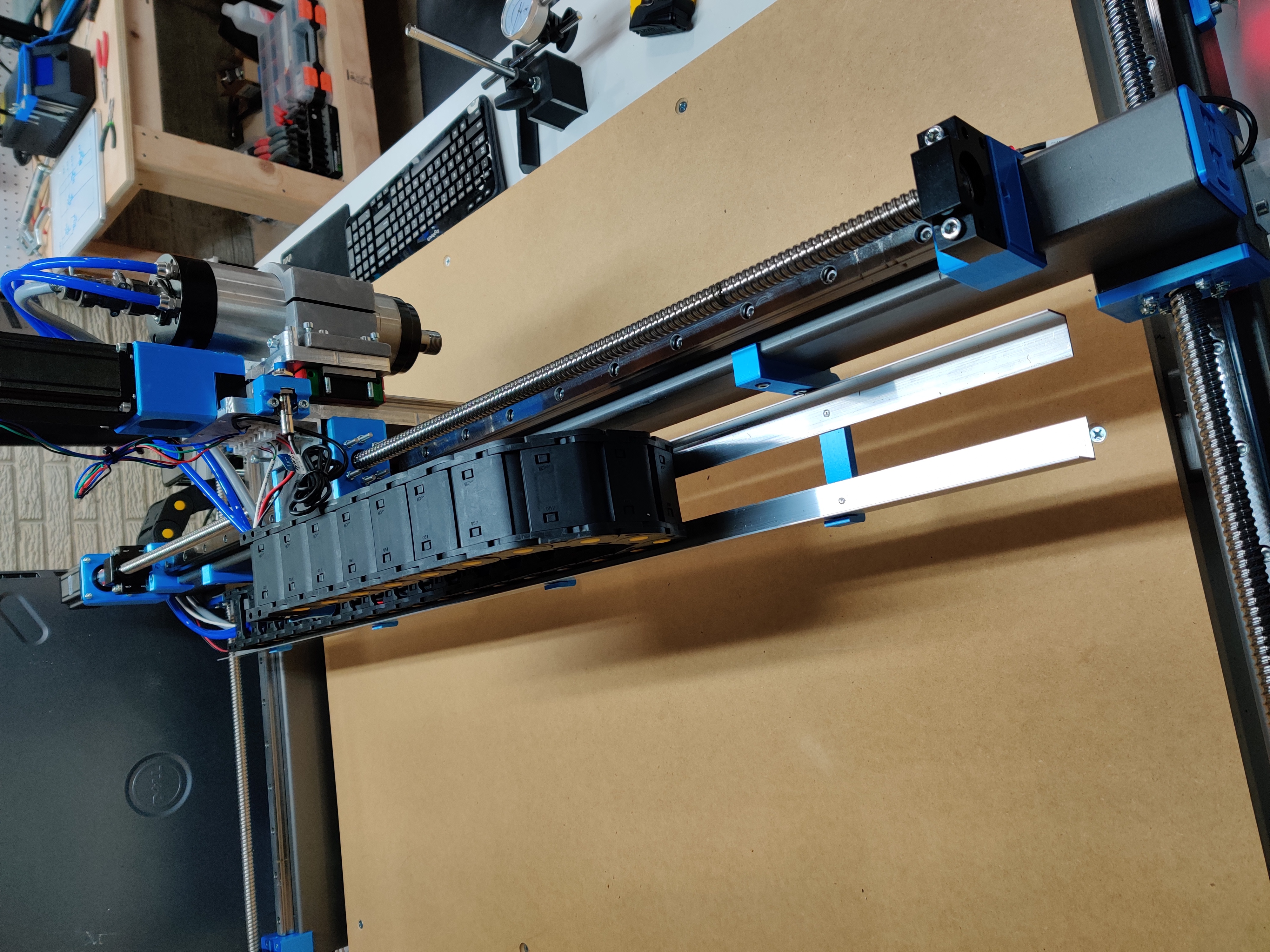
¶ Q - Did you end up putting angle aluminum on the back of the X to support the X drag chain?
¶ Q - @ReduX_Hz I have been meaning to ask: In one of your videos you had a part on the back of the ball screw that looked like a printed part. It might have just been the Y roller but it didn't look big enough. You slide it up the screw and press it against the ball screw. Which part is that?
ReduX_Hz: oh that's the front and rear plate on the Y roller
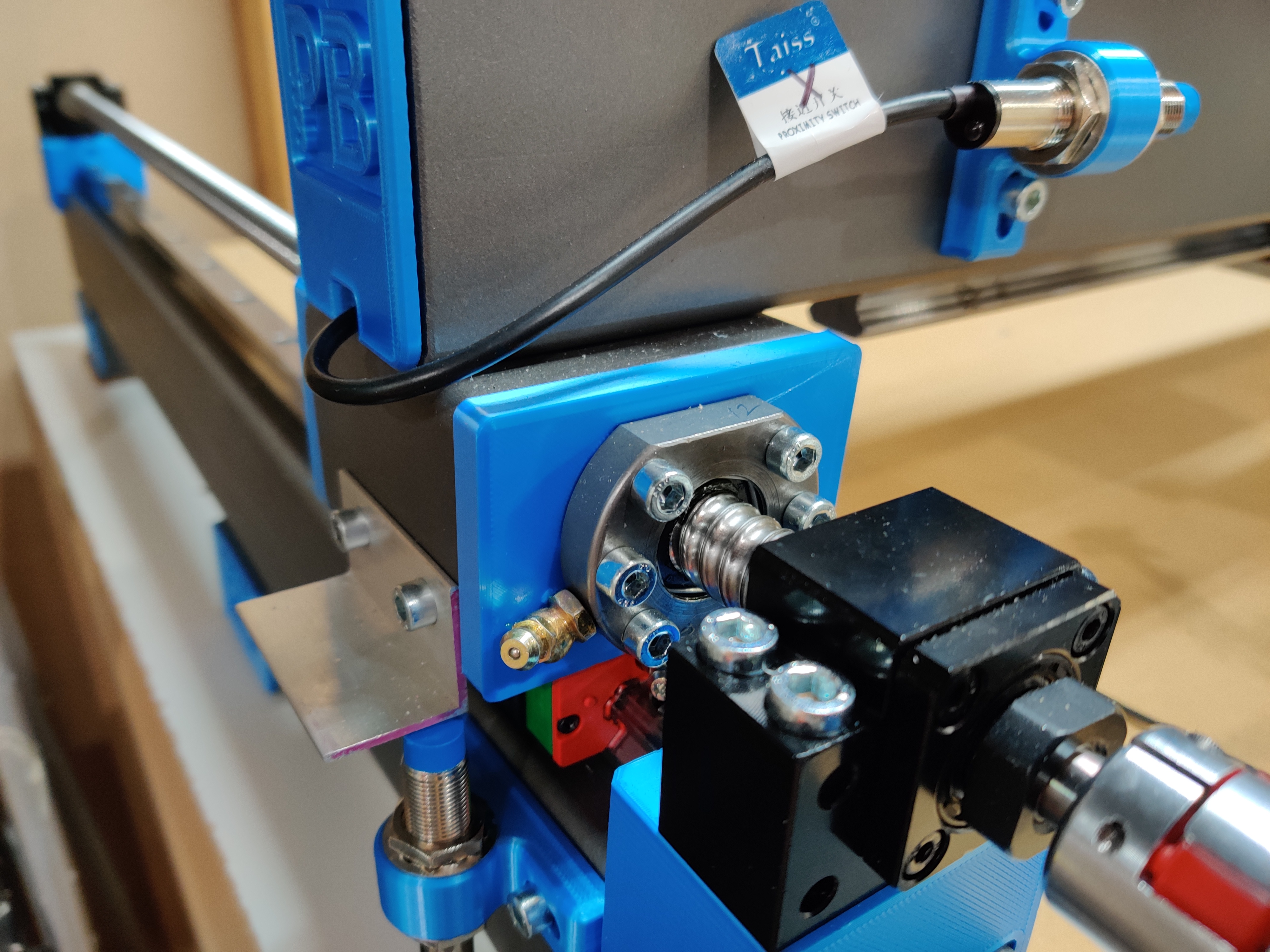
Right?
Trader: Ah ok, it was the roller plate after all. I think it was just maybe the view from the back that threw me. Oh what is that zerk fitting? That's the ballscrew zerk? Is that one of those ones from your amazon list and does it clear the standard plate or did you need to make a bit of clearance in the Y roller plate for it?
ReduX_Hz: yep it's on the amazon wish list, i don't think it clears the plate though, i think i put it on before the y roller plate. get zerks on and grease as soon as you can to avoid clearance issues later
Trader: So did you end up cutting away a bit of the face or is there just pressure on the Zerk in the photo?
ReduX_Hz: sorry, i misread your message, it does clear the plate, however since its angled it will hit the y roller plate when you rotate it
Trader: And is that bit of angle aluminum just to give you material for the sensor to read that is mounted on the Y rail?
ReduX_Hz: yep
¶ Q - I just found out that my pnc isn't 100% square. The distance between the BK blocks is 3mm wider than between the BFs. So what to do? Can this be compensated by software or should I try to adjust it? As the machine is already standing, it's pita to reach all screws. 3mm is not that much on a length of 750mm though.
Ljkenny: Yes, you square up in S/W. Do you have sensors on both Y1 and Y2?
Sebastian: Yes. On both ends. So no need to fix it in hardware?
Ljkenny: Once you can cut, get it to drill 3 holes in the shape of an equilateral triangle
Sebastian: I know the method
Ljkenny: Okay, once you have your offset, plug that onto LinuxCNC. I did and I'm pleased I did it. Took about 2hrs.
Logan: Uh, if your X distance between BF is 3mm difference than between BK that's a problem. If it's diagonal not so much
Sebastian: Ok why so?
Logan: Well your rails have to be parallel for your gantry to work
Ljkenny: Oh, like a trapezoidal? Can you run your gantry the full length?
Sebastian: Gantry is moving quite smooth
Logan: Right. You can fix a trapezoid. You can't fix a rhombus
Ljkenny: So it's probably parallel then
Sebastian: I have a trapezoid
Ljkenny: You'd think your gantry would pinch at one end if that were the case?
Logan: Mine was about 3mm out of square, loosened the bolts and hammered on a block of wood and got it within 1.3mm, close enough. Yeah unless something is loose enough for roller to slide, or the rail isn't parallel to the steel...
Ljkenny: Right, that was my next Q: are you tight?
Sebastian: Yes
Logan: Get your wasteboard cuts accurate, square your frame to your wasteboard then center your left rail, loosen the right one and tighten it as you move your gantry
Trader: Yeah that's the kind of thing I'm thinking... and also perhaps it's worthwhile to do some measuring checks at that stage where you screw down the first and last bolt in the linear rail?
Sebastian: This dialogue encouraged me to go the hard way tomorrow. Thx :) Loosen all screws and get that damn thing physically square. Which means that I have to lift it off the workbench. As its standing in a corner atm.
Trader: Logan, Your suggestion about getting a nice square wasteboard and using it as a known reference against which the drilling and assembly could be done it interesting. Works better at smaller footprints, in terms of manageability…
¶ Q – What is the weight of the assembled Z?
hoges: ~18kg I think we have calculated
¶ Q – Should I put my inductive sensors inline somehow or at a right angle above the travel path on the axis?
Logan: Either work. I like inductive out of the collision path. The other thing is I don't want to have to dismantle the riser to replace a part that stopped working. And having all the sensors on the gantry means I can wire them all to a central point and run one cat5 cable back to the controller
¶ Q – How did you cut the notch out for your Z carriage angle aluminum for the zerk fitting access to the carriages?
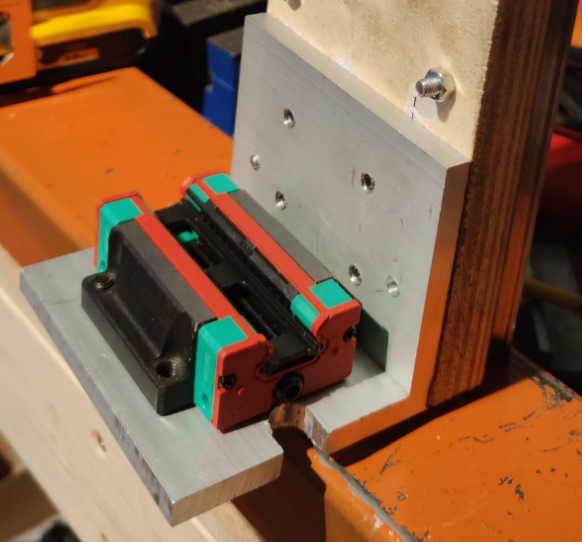
Trader: What was your method? Drill a 1/2" hole on the press and jigsaw it out to the edge? [previously noted that hand drilling this piece can be challenging]
ldc79: I used a hand saw. I used too many power tools
Logan: Yep, or hacksaw, grinder, Dremel, whatever you have on hand
Trader: I'm realizing a trim router and a router template could do it as well but probably much faster to drill and saw
¶ Q – Given the smaller size and different mounting collar, does the Makita collet nut reach the wasteboard the same way the water cooled spindle does?
Trader: Does it get the collet nut to roughly the same spot?
Logan: Not quite but it'll reach with a 1" tool stickout to a 3/4" baseboard, and easily reach a doubled wasteboard+baseboard
¶ Q - Been looking at many option and still can’t decide: tracks, inserts, nothing (just wood screws)... Or make a combo of all that?
Logan: These I think are pretty swell. https://www.aliexpress.com/item/1005001679942083.html they're 30mm wide so you can mill your own inserts or use these long ones... https://www.aliexpress.com/item/1005001679489170.html
Then there's this with a built-in spot for a measuring tape. https://www.aliexpress.com/item/32979624667.html
¶ Q - Any suggestions for what to look at to fix wobbly stepper motors?
m0jo: My wobbly steppers problem was completely fixed by using Oldham coupler. They are a lot more forgiving for the misalignment between the stepper and the ballscrew compared to the default plum coupler.
kotlikm: Have a link? Mine are pretty wobbly.
m0jo: https://www.aliexpress.com/item/32869390161.html
GHPC-26X30.4 is about the same size as the plum coupler, just insert a note when ordering so they send the appropriate shaft size for your stepper/ballscrew combination
Logan: They are about 5x more expensive. I suspect most of the alignment issues people are having are from tight-fitting bolts threading into the plastic and then pushing the BK and motor block out of alignment when screwed down. Drill your bk riser and motor block out with a 6mm drill bit first, see if that fixes your wobble. And check for elephant's foot on your print as well, that can also be a problem.
m0jo: I would assume part of the difference in cost is the free fast shipping and the order qty, Oldham coupler don't really have complicated features or weird materials compared to the plum coupler, the moving part is a bit of plastic and the jaw are shaped differently.
Logan: so not quite 5x, about 3x. Here's 4 of the plum couplings for a few dollars more. https://www.aliexpress.com/item/32958487946.html alignment issues are printed part issues though, you'll fix them by fixing the parts problems.
ldc79: this is what I discovered a couple of weeks ago. it fixes most of the issues
hoges: I opened out the holes on the motor mounts, still not sure what I was thinking when I put those dimensions in but they are fixed now
ldc79: No biggie, it was an easy fix