In case of a discrepancy between the Fusion 360 CAD model and this Wiki, assume the CAD is accurate as the wiki might be outdated. This holds especially true for bolt types and locations.
¶ Want to paint the frame first or finished initial assembly? go here for painting > https://wiki.printnc.info/en/v4/painting
¶ Introduction
This build guide will walk you through the tools, materials, and process to build your own PrintNC. It's intended to be complete with all the information you will need for the full build process, but you may not find it easy to digest. Please watch a few video guides before starting your build for a better overview of the process. The build steps sections can be followed step-by-step on a digital device to help ensure no critical steps are missed or done wrong (and to save some trees).
¶ Required Tools and Materials:
- Hand drill or drill press
- Metric drill bits (6.5mm, 5mm, 4.2mm or 3.3mm)
- Metric taps or drill/tap combo bits
- Metric hex keys
- Small 90 degree ratcheting screwdriver with 5-10 degree clicks
- Measuring tape
- Center punch
- Awl/scribe
- Machinist or combination square
- Digital calipers
- Double sided tape
¶ Frame Assembly Printed Drill Guides:
- #1 X-Frame
- #2 Y-Frame,
- #3A Y-Frame BF
- #3B Y-Frame BKHM
- 2 or more YRail Centering Guide
- Both Radius Tools
¶ Important Notes
- Never remove the ball screw nuts from the threaded shaft. You may lose some ball bearings, and they can be extremely challenging to replace accurately.
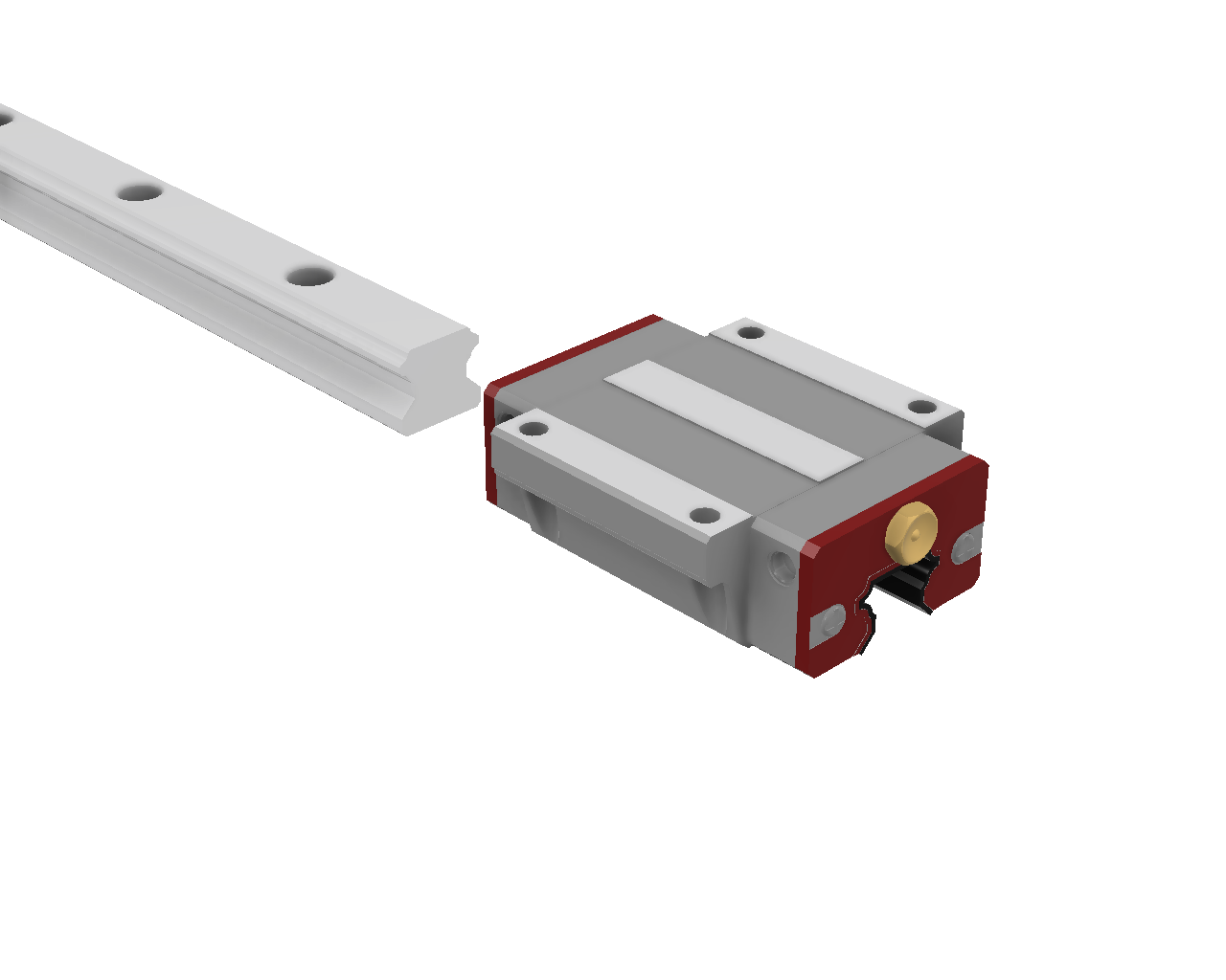
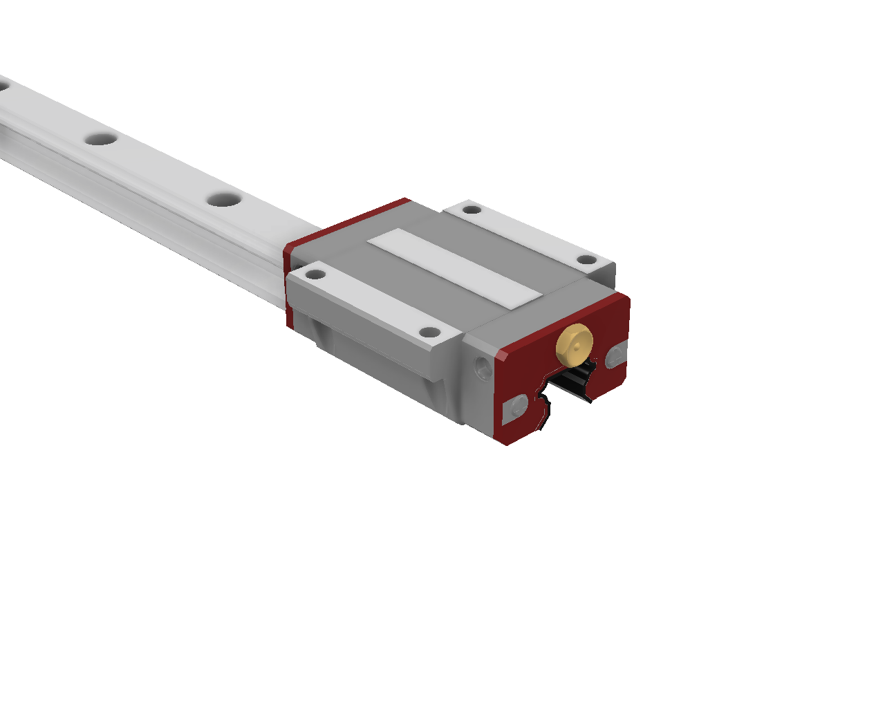
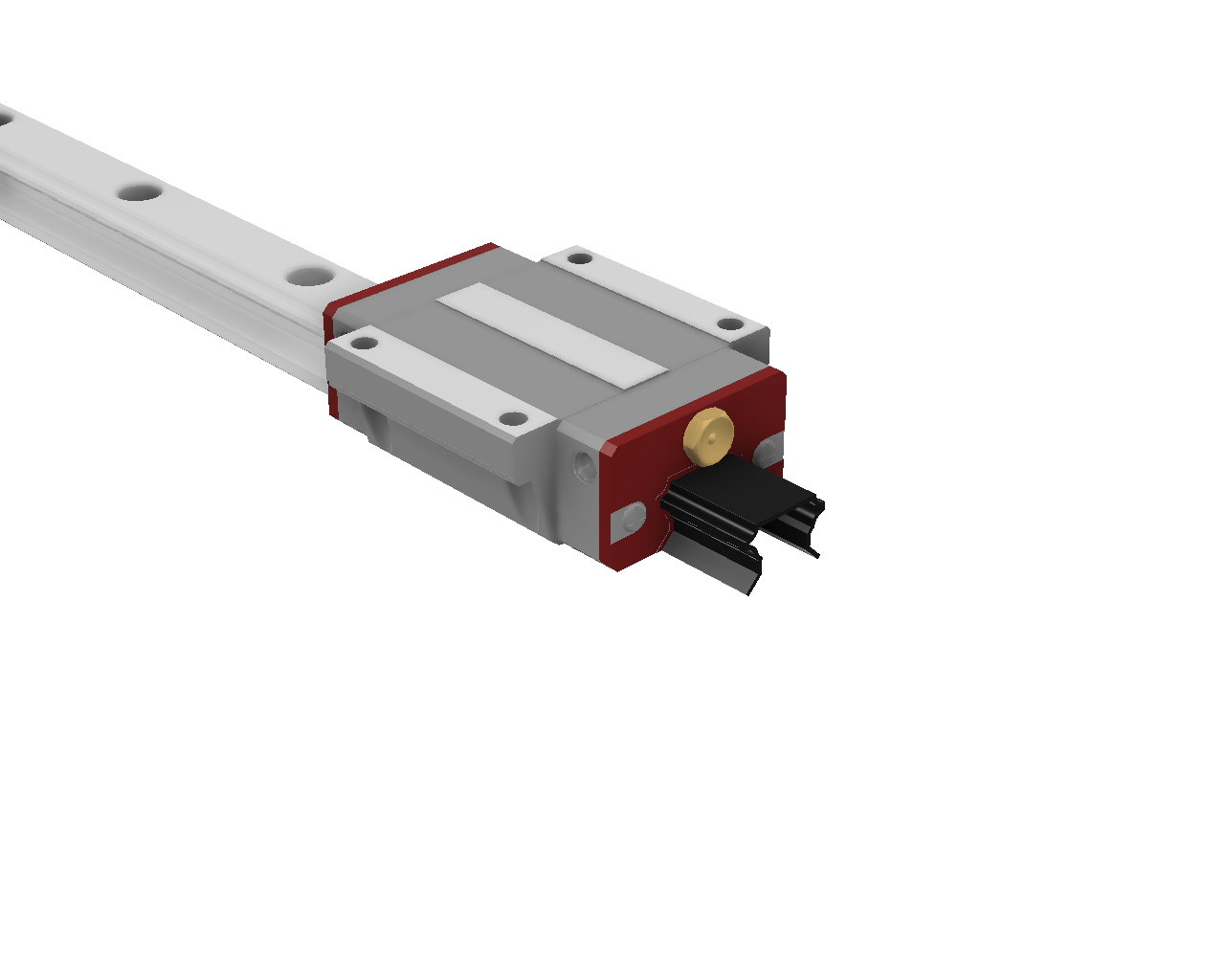
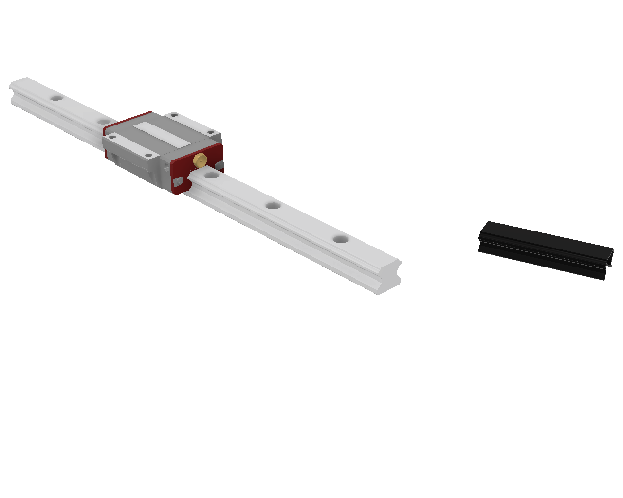
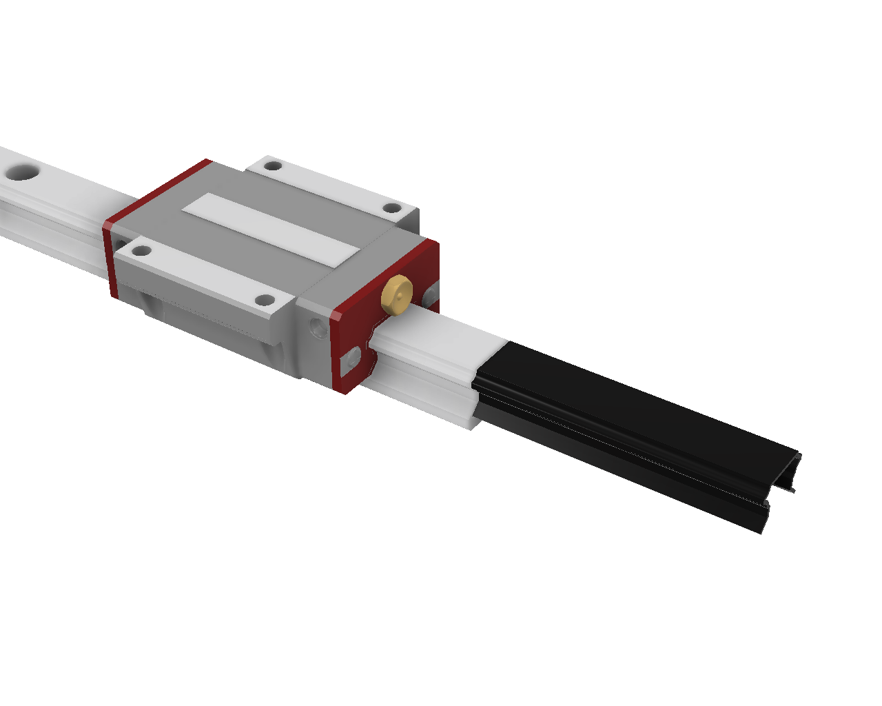
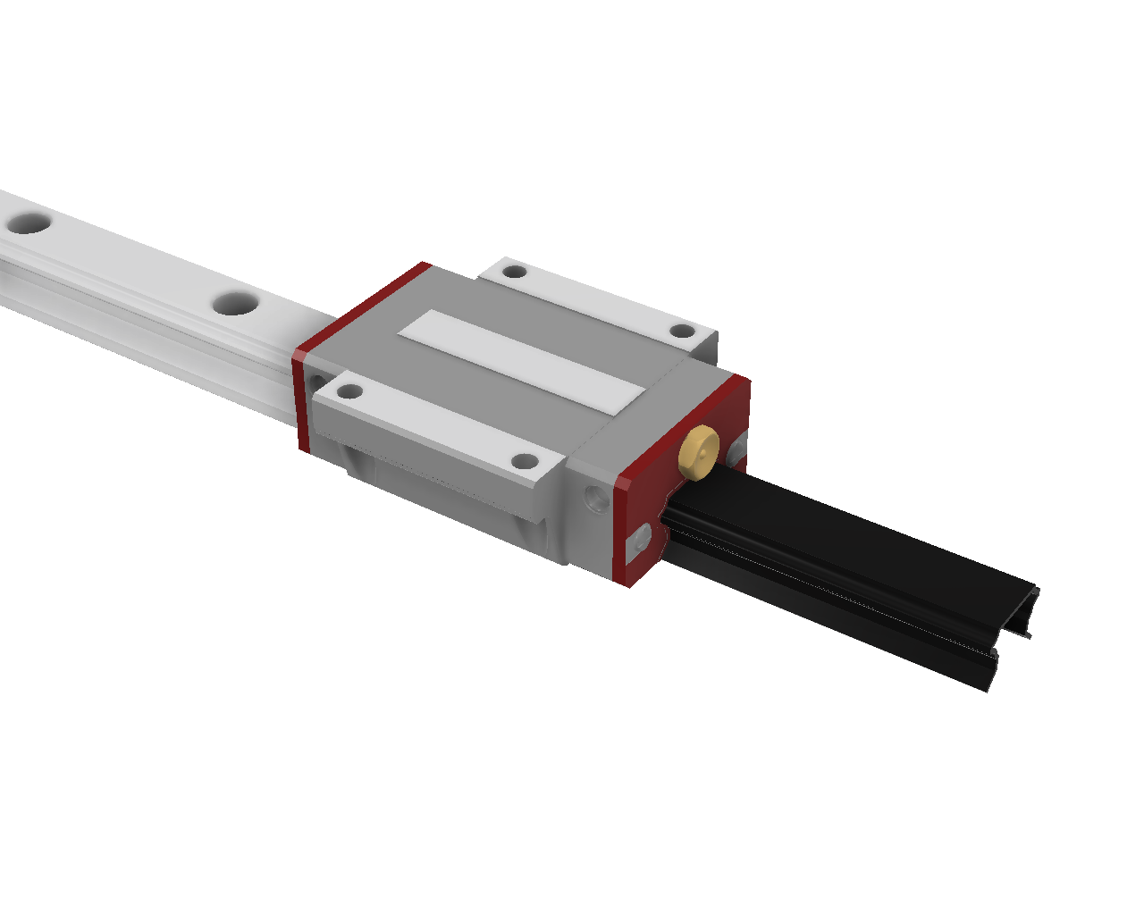
- When receiving the HGW20CC linear rails carriages, you'll see that there are delivered with a small plastic part in the carriage's groove. This is to secure the steel balls in the carriage. After mounting the carriages to the linear rails, keep those plastic parts and store them in a safe location. You may need them if you have to remove the carriage for any reason.
- Several steps in the build process require using a small allen key to pass through a small hole to tighten bolts. This limits the types of bolts in several places to button head style, since those use smaller allen keys. Please make sure you’re using the correct style of bolts where needed. Ball-nose allen keys with long shafts are required for these sections.
- Some build steps can be done in alternate order to reduce tool changes or to accommodate the constraints of optional tools like drill presses. Some known alternatives include:
- Combine some steps : Y Axis Frame - mark corners and middle, then flip over and mark BF12. All are M6 Threaded.
- Generally, build steps are ordered in logical sequence : a threaded hole is first marked, then drilled, then threaded; then the manual continues with the next group of holes. You could (if you prefer) first drill all holes and then thread them, but if you do so, pay attention not to mix up the drill and tap sizes !
- The instructions call for you to drill and tap all holes separately, but if you have a combination drill and tap bit you can use it to significantly cut down on your build time.
- Any time you see drilling or tapping in metal, always add a lubricant. You can find some cutting oil at any hardware store. A regular oil is also perfectly suitable. Not applying lubricant will increase heat during drilling and tapping operations, which can have many side effects :
- increased tool wear
- less clean holes or threads
- risk of breaking the drill or tap bit
- Use the 3D printed guides to mark hole locations on your steel accurately. The best tool for this is a transfer punch, which comes in different sizes to match the hole size and make an exact center mark. If you don't have a transfer punch, use a center punch. Make sure the center punch fits snugly in the guide and doesn't move. If it's too small, wrap tape around it until it fits. You can also use a drill bit of the right size, but tap it lightly. After making the initial marks, use a normal center punch to enlarge them. It’s best to make small marks first, check your measurements using the guide, and then enlarge the mark. If needed, you can adjust the mark by holding the punch at an angle and tapping it to move the mark in the desired direction.
- For the holes that need to be precise (like the ones you're going to tap), be sure to use a good sharp drill bit. Start by drilling pilot holes at least 1.5 to-2 mm smaller than your finish hole size. Then, check your pilot holes against your guides before enlarging. If the pilot holes are not in alignment, you can sometimes get a hole to move back in the direction you want by sizing up by 0.5mm and angling the drill bit.
- Generally every bolt or nut should be secured with threadlocker to avoid loosening from vibrations. Medium strength (e.g. blue loctite) threadlocker can be used on all threads from the beginning. When high strength threadlocker is used, it should only be applied during the last tightening of that screw, e.g. after painting and squaring the frame.
¶ Videos you may want to watch before assembly:
- Walkthrough by @hoges
- Projects By Brian
- Arya Nakh
- Mudd Flapp
- Mitch 3D
- Helpful video from @hoges showing how to drill and tap using the guides (note he did this very quickly, you'll want to go slower and make sure everything is lined up)
¶ Before You Start
Pick a side of your bench (left or right) that your electronics cabinet will be mounted on, and then plan your machine layout to match: X stepper, Y cable chain and electronics cabinet on the same side of the machine will minimize cable lengths. The guide assumes a right side X stepper and Y cable chain, but that's not a requirement. Just mirror the instructions for the X axis stepper, rails, ballscrew and X/Y axis cable chain installation.
Ensure you have measured the exact dimensions for each aluminum angle and steel tubing - height, width, thickness and radius, and entered these values into the PrintNC V4 CAD before 3d printing. Radius can be approximate (closest 1mm), but the drill guides and printed endcaps require accurate steel and angle dimensions. Use the Radius Tools included in the Printed Drill Guides section of the CAD.
Check the length of the X frame tubing against each other and ensure they are close to the same length (within 1mm). Repeat with the Y tubing and rollers. If the lengths are different, it complicates the build process slightly. Either grind or file or sand down the tubes to make them the same length, or make a note of which X frame and Y frame tubing is longest and mark it (it’ll be the reference steel for layout).
¶ Carriage Preparation
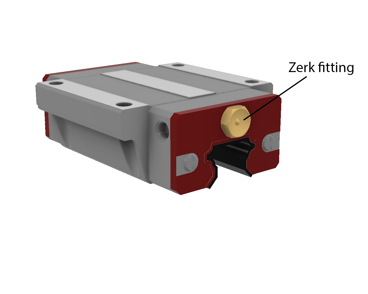
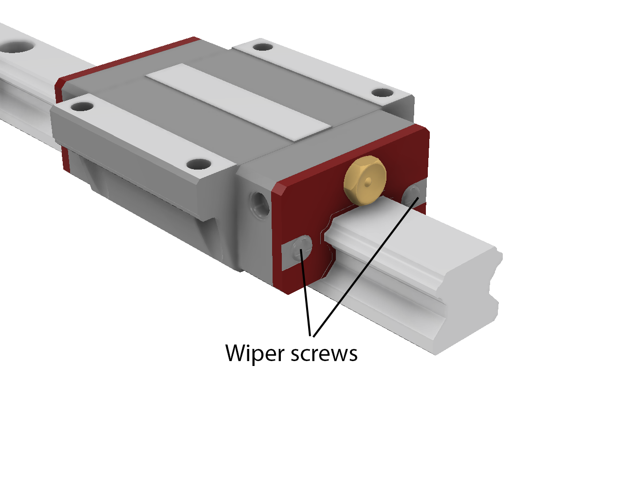
Install a 45 degree zerk fitting (or low profile or needle type fitting) on each carriage, loosely. Place each carriage carefully on a rail and loosen the wiper screws, then tighten the wiper screws and zerk fittings. Ensure each carriage rolls smoothly. There will be some resistance, especially once lubricated. Remove the carriages carefully by reinstalling the carriage keepers for each to keep the bearings from falling out.
¶ Components
 |
 |
¶ Insert carriage
|
|
|
|
¶ Remove carriages
|
|
¶ Frame Assembly
¶ Drill Guides
- #1 X-Frame
- #2 Y-Frame
- #3A Y-Frame BF
- #3B Y-Frame BKHM
- 2 or more YRail Centering Guide
¶ Step 1: X Frame Tubing Top and Bottom Side
Drill - 6.5mm
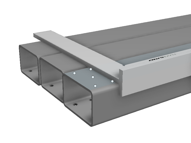
Layout the hole locations on the top and bottom of the X-Frame tubing using #1 X-Frame drill guide placed on the end of the tubes.

If your X-Frame tubing lengths are not the same, use the drill guide to mark the longest tube. Align the far end of all tubes, and use a combination or machinist square to mark where the holes should be on each tube. Place the #1 X-Frame drill guide over the marked hole locations and punch the holes. This will make sure the Y-Frame steel tubing is parallel and will make aligning the Y-Rails easier.
¶ Step 2: Y Frame Tubing Bottom Side
- Drill - 5mm, tap - M6 for M6x12 bolts
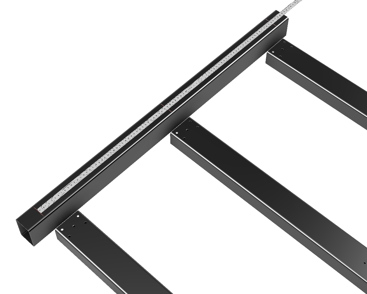
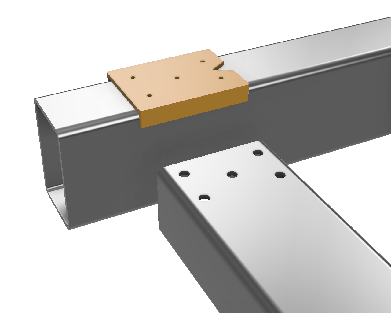
Layout the hole locations on the bottom of the Y-Frame tubing. The default V4 design places the front and back X-Frame tubing 50mm from the ends of the Y-Frame tubing. Measure 50mm from one end and scribe a mark, then measure the distance between steel tubes in the cad (front face to front face) and make your remaining marks the same distance apart, then align back edge of #2 Y-Frame drill guide with the scribed mark on the longer tube (if there’s a difference in length) and then transfer the marks between them using the combination or machinist square.
 |
 |
 |
¶ Step 3A
- BF and BKHM - Drill 5mm, tap M6 for M6x30 bolts
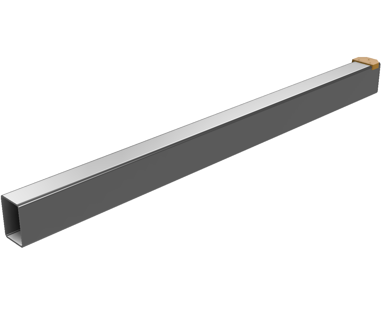
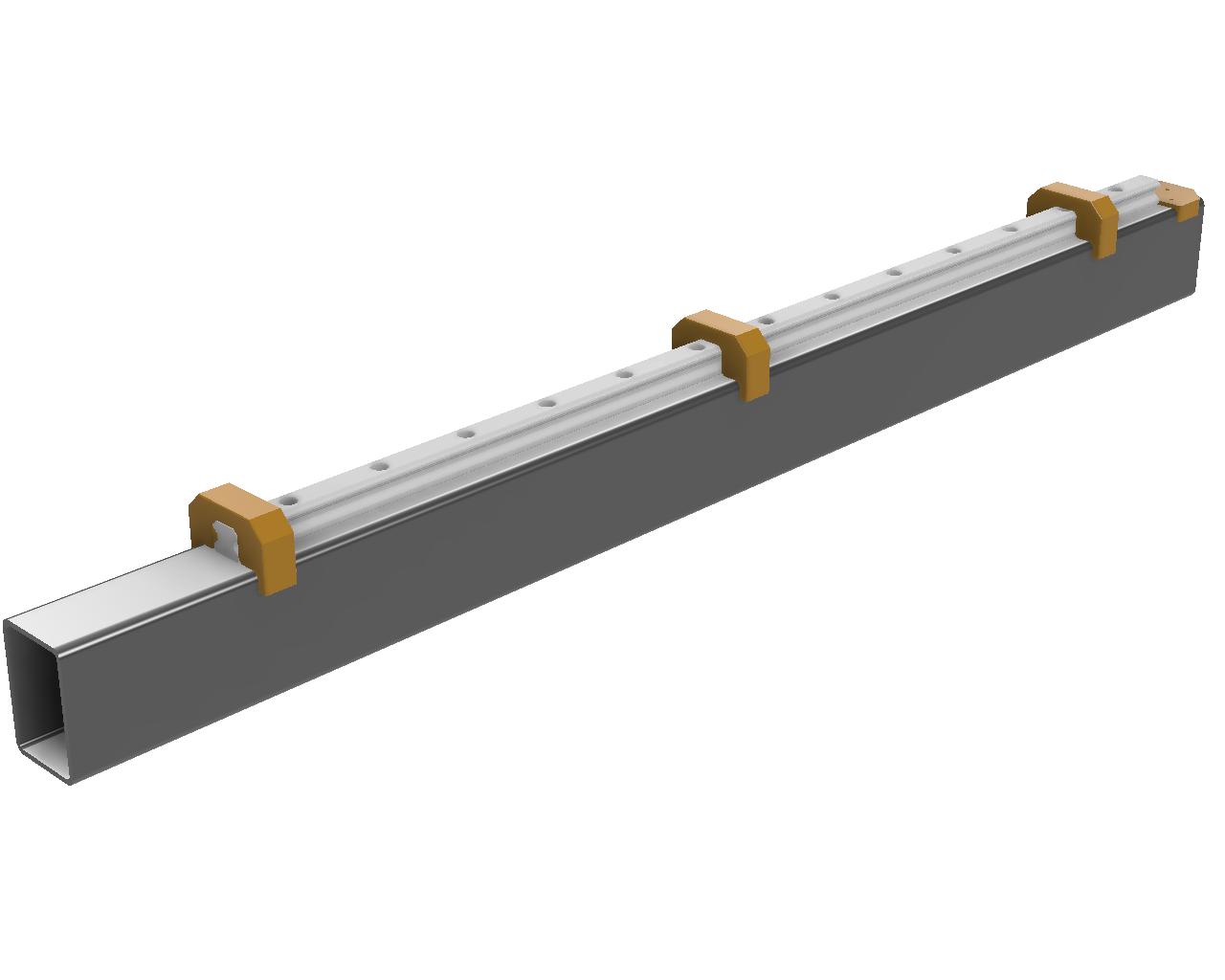
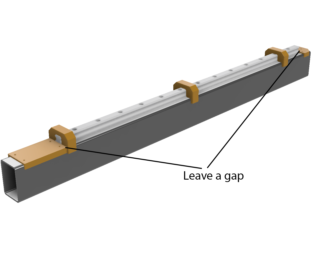
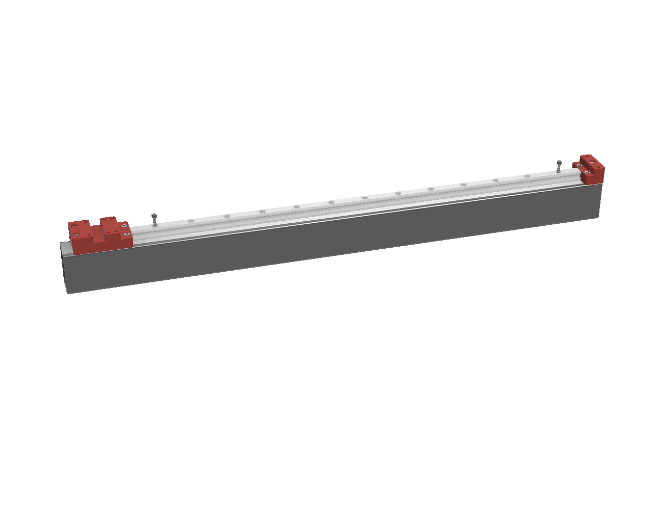
Layout the hole locations on the top of the Y-Frame steel, starting with the #3A Y-Frame BF drill guide at the back of the machine, then place the linear rail against the drill guide, and place the #3B Y-Frame BKHM drill guide against the other side of the rail. Leave 0.5-1mm gap at both ends of the rail to make assembly easier. Use the YRail Centering guides to hold the linear rail in place.
 |
 |
 |
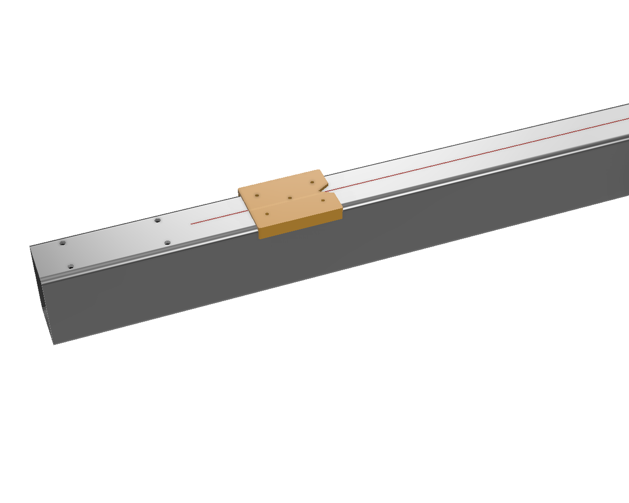
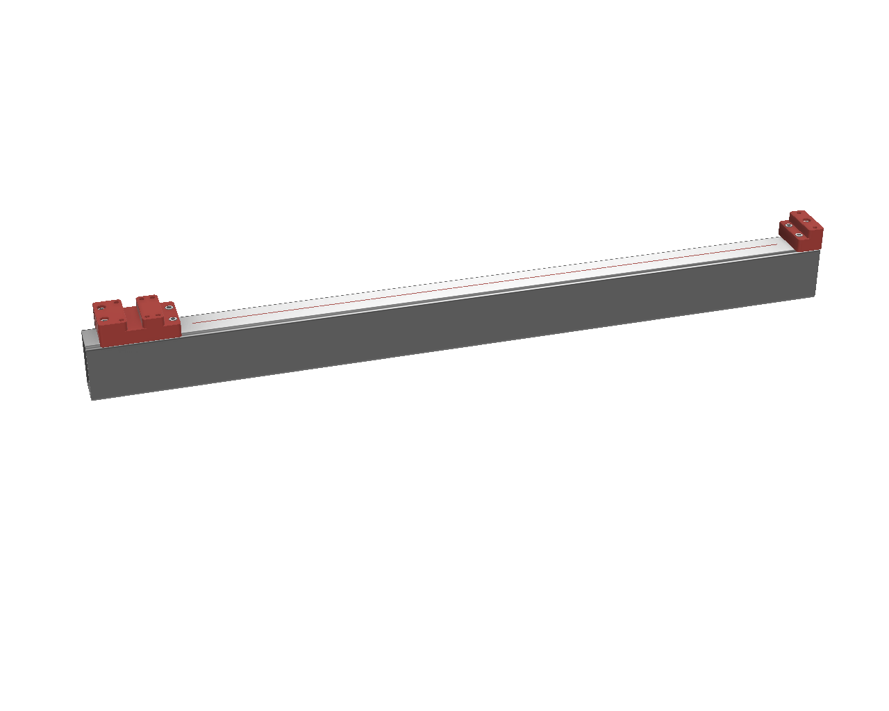
Remove the drill guides and rail and use the V in the #2 Y-Frame drill guide to scribe or pencil a center line down the steel for the rail center. Drill and tap the BF and BKHM riser holes and install both risers.
 |
 |
¶ Step 3B: YAxis Linear Rail
- HGR20 - Drill 4.2mm, tap M5 for M5x20 bolts
- HGR15 - Drill 3.3mm, tap M4
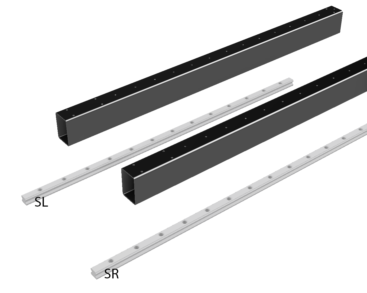
Mark the first and last holes of the linear rail, and drill and tap them first, and install bolts in them to prevent the rail from shifting while marking the remaining holes. Center punch the remaining holes, then mark the end of the rails facing the stepper with SL and SR before removing from the tubing. Ensure the center punch marks are aligned with the scribed or penciled center line before drilling and tapping.
 |
 |
¶ Frame Assembly
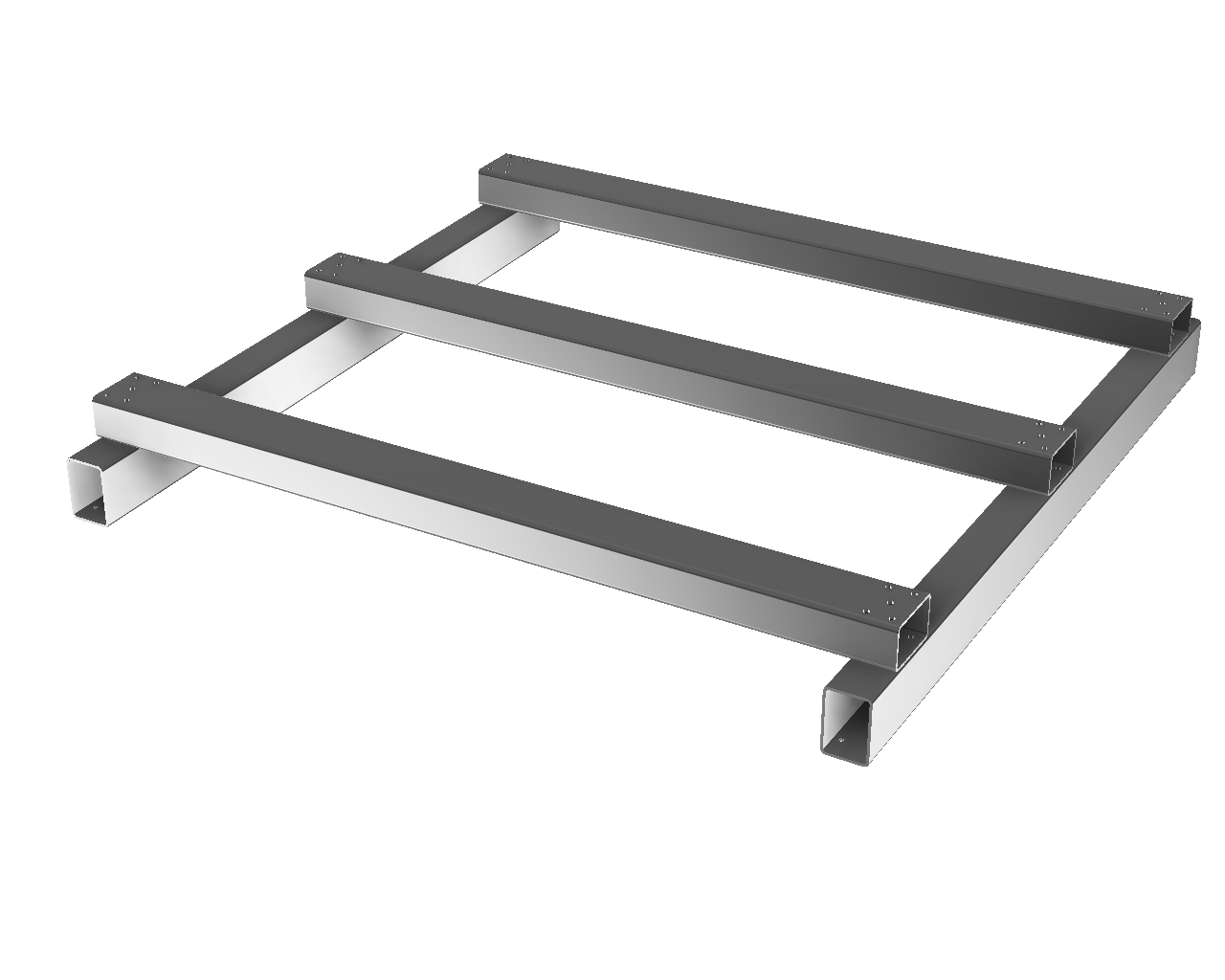
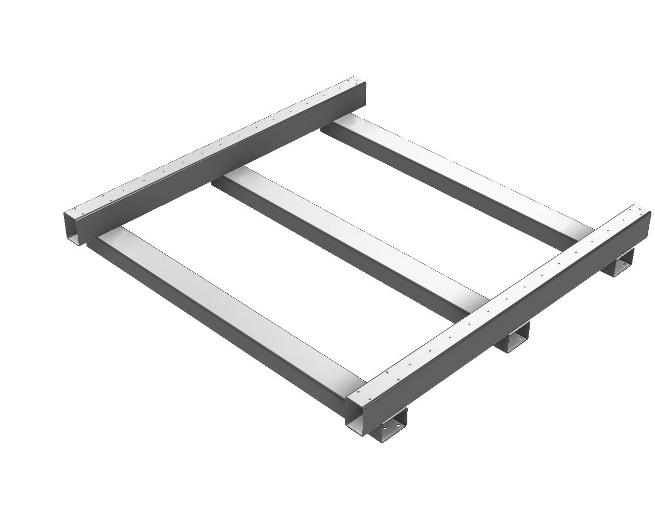
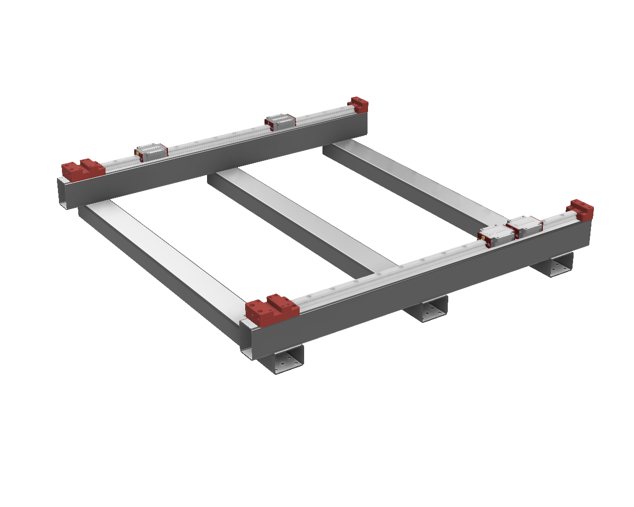
Place the Y steel on your workbench upside down with the BKHM mount side facing forward. Place the X steel tubing on top, welded side facing up, and install the bolts. If you cannot install all the bolts because the holes don’t line up, don’t panic. Drilling a hole or two larger in the X frame steel is a common fix for misaligned holes.
Once all the bolts are installed, turn the frame upright and bolt on the BF and BKHM risers. Install the carriages that have been prepared in the Carriage Preparation step above on to both Y rails (for dual carriages per rail, front carriage zerk forward and rear carriage zerk backwards), and then bolt down the rail to the top of the Y-Frame tubing.
 |
 |
 |
¶ Frame Alignment check
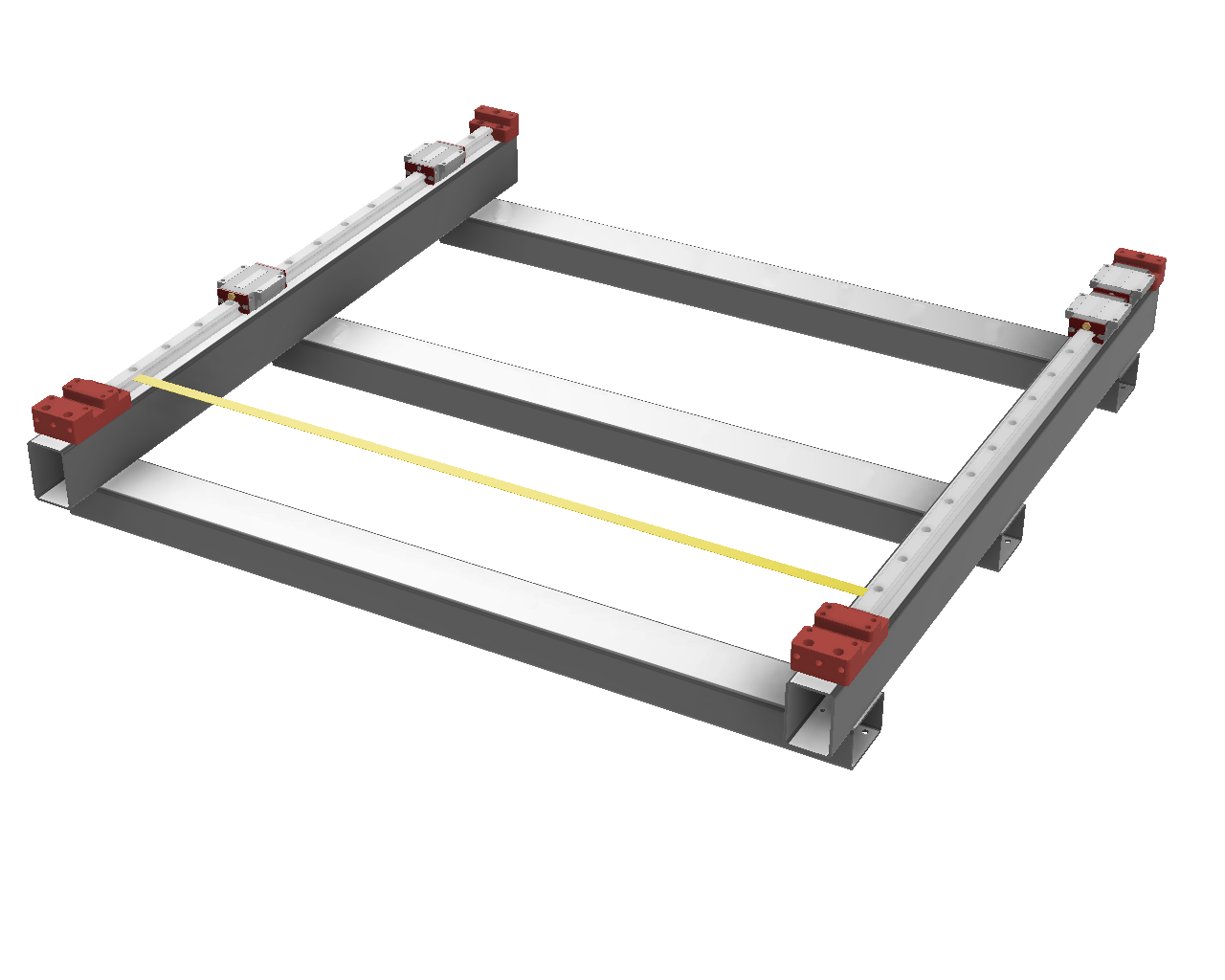
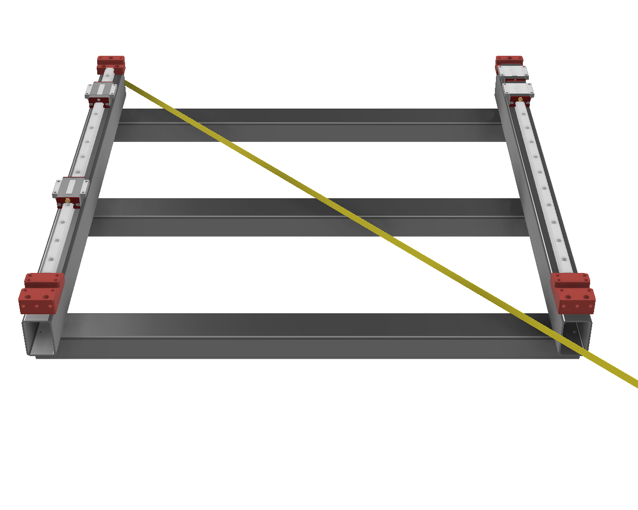
At this point it’s a good idea to see if the frame is aligned well. Using the tape measure, move along the Y rails and note if they are relatively parallel or not. There’s some adjustment in the rail bolts so they don’t have to be exactly parallel at this point but less than 0.5mm is needed. If they’re not parallel enough then the bolt holes in the front and rear XFrame tubing may need to be drilled larger to allow the Y frame to pivot slightly.
With the Y rails parallel, next check corner to corner for equal. That plus the parallel above confirms the frame is square. Easiest way to accomplish this is hook the tape measure on the rear inside vertical edge of the YFrame tubing and measure to the opposite side front inside vertical edge. Adjust for square and tighten a few of the bolts to keep it that way.
 |
 |
¶ Gantry Assembly
¶ Drill Guides
- #4 YRoller-Carriage
- #5 YRoller-Gantry
- #6A Gantry-YRoller
- #6B Gantry-YRoller Brace
- #7A XGantry-BF
- #7B XGantry-BKHM
If your gantry width is the same as the YFrame width, you can use #2 guide in place of #6, #3B guide in place of #7B and reuse the YRail Centering Guides for X.
¶ Step 4: Bottom of Y Rollers
- HGW20CC - Drill 6.5mm
- HGH15CA - Drill 4.5mm
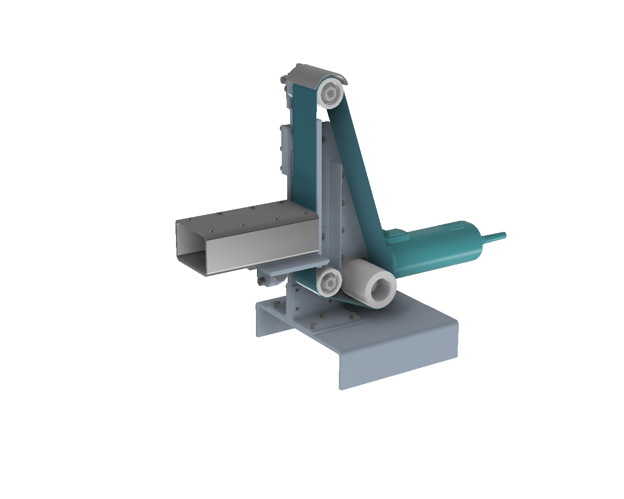
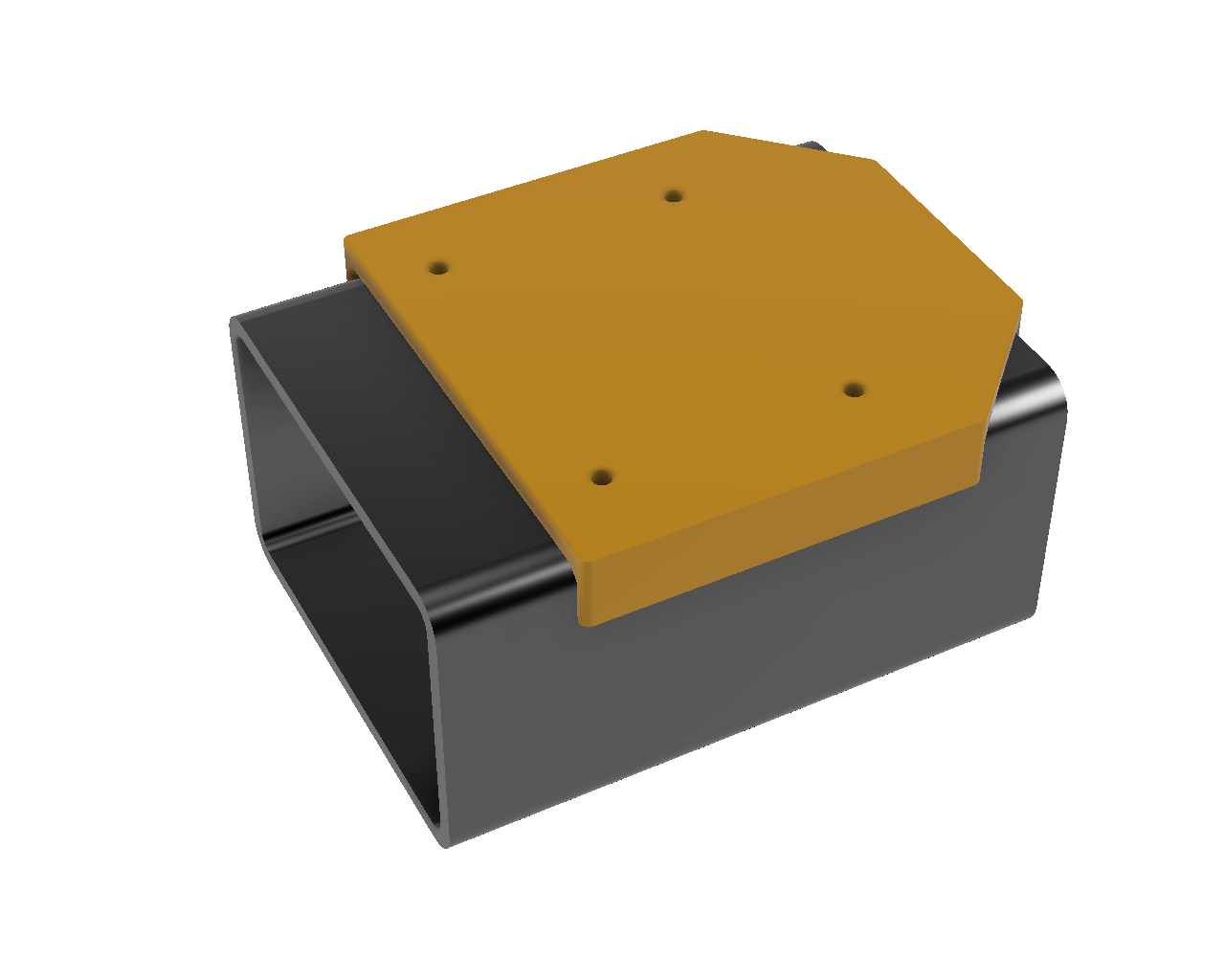
Use the combination or triangle square to determine which end of the Y-Roller tubing is the closest to square both horizontally and vertically. Mark this end using a scribe or chalk. Use #4 YRoller-Carriage drill guide to mark the carriage holes. If you have dual carriages, use the same drill guide aligned to the front and back side of the roller.
 |
 |
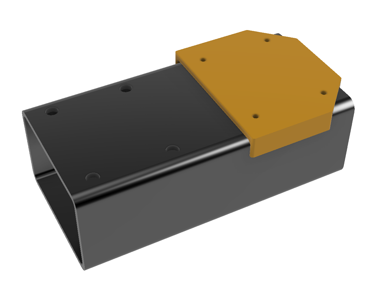 |
If the nut plate side roller face is more than a tiny bit out of square, the ballscrew nut will bind when tightening the roller plates. There are several ways to resolve this; angle grinder, bench or handheld sander, or course file. You will need to scribe a line around the end of the steel tubing and then grind/sand/file until the line is parallel to the end of the tube. Alternately you can shim between the roller face and roller plate.
¶ Step 5: Top of Y Roller
- Drill 5mm, Tap M6 for M6x12 bolts
Use #5 YRoller-Gantry drill guide aligned with the back of the YRoller (opposite the side you’ve determined to be the most square or have processed to be square in the step above), mark, drill and tap the holes for the gantry. Install the rollers on the carriages using M6x12 bolts for HGW20CC and M4 bolts for HGH15CA.
¶ OPTIONAL for YAxis Roller with Dual Carriages:
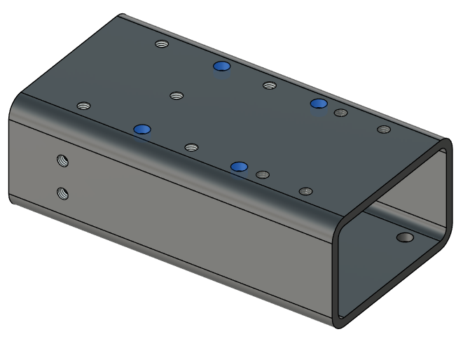
It's difficult to reach the bolts in the center of the dual carriage YRoller, so optionally you can drill the center 4 holes in the top of the Y rollers, provided they don't conflict with the holes for the Gantry or Gantry Brace. Use the two holes closest to the center of the #4 YRoller-Carriage drill guide to mark after confirming there's no conflict in the CAD as shown below.
¶ Step 6A: Gantry Prep
On the top and bottom sides of the gantry, measure YRollerWidth + 5mm for dual X carriages (80mm for 50x75mm rollers) or YRollerWidth + 25mm for single X carriages (100mm for 50x75mm rollers) on the end opposite your XStepper, Y cable chain and electronics enclosure, and scribe a mark, then place an Xaxis Linear Rail on the mark and scribe a second mark at the far end. Then use the V slot on the #6 Gantry-YRoller drill guide to mark a center line from the scribe mark to the other end of the linear rail.
If your gantry width is the same as the YFrame width, you can use #2 guide in place of #6.
¶ Step 6B: Gantry Bottom to Linear Rail
- HGR20 - Drill 4.2mm, Tap M5 for M5x20 bolts
- HGR15 - Drill 3.3mm, Tap M4
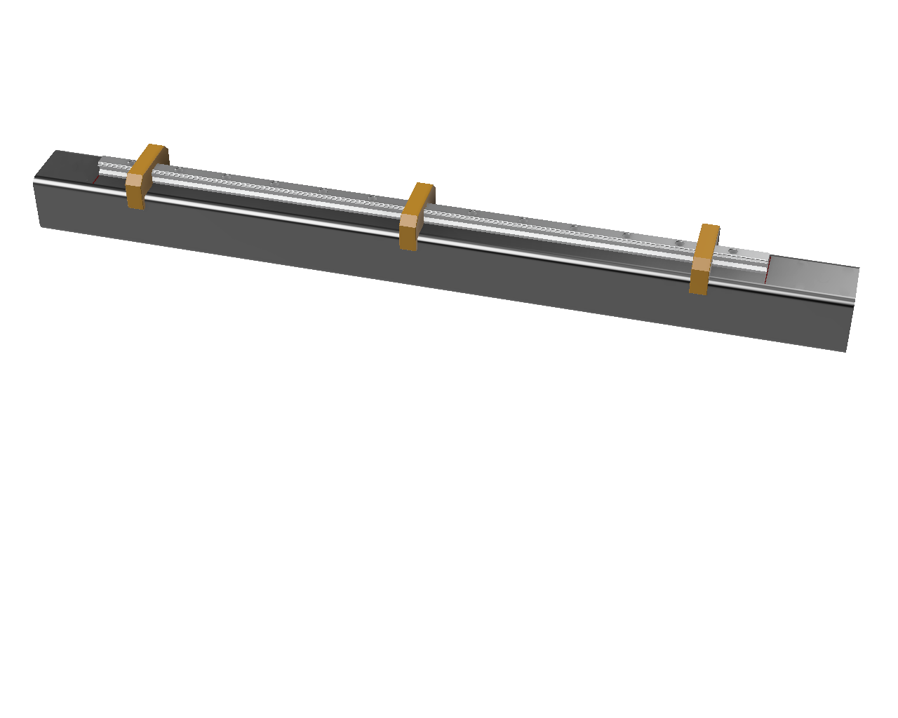
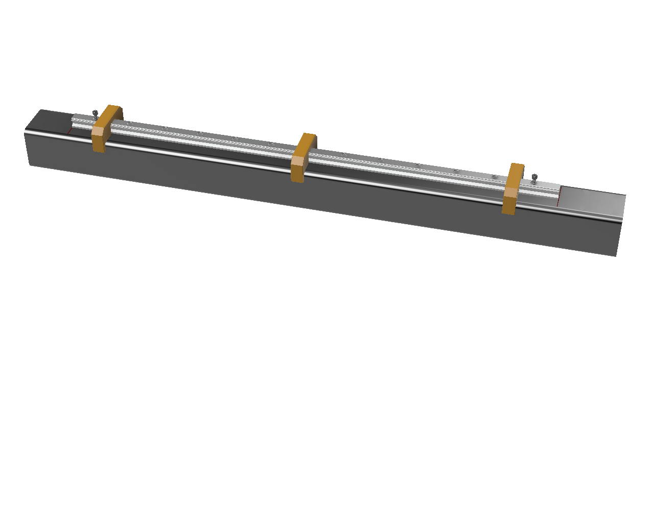
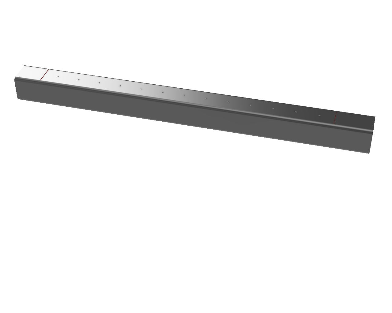
Align one of the X linear rails between the marks from the Gantry Prep step above, use the XRail Centering Guides (or reuse the YRail ones if Gantry and YFrame are the same width) and mark the first and last holes for the rail, and drill, tap and bolt the rail on before marking, drilling and tapping the rest of the holes. Ensure the center punch marks and drilled holes are aligned with the centerline scribe mark as you go.
 |
 |
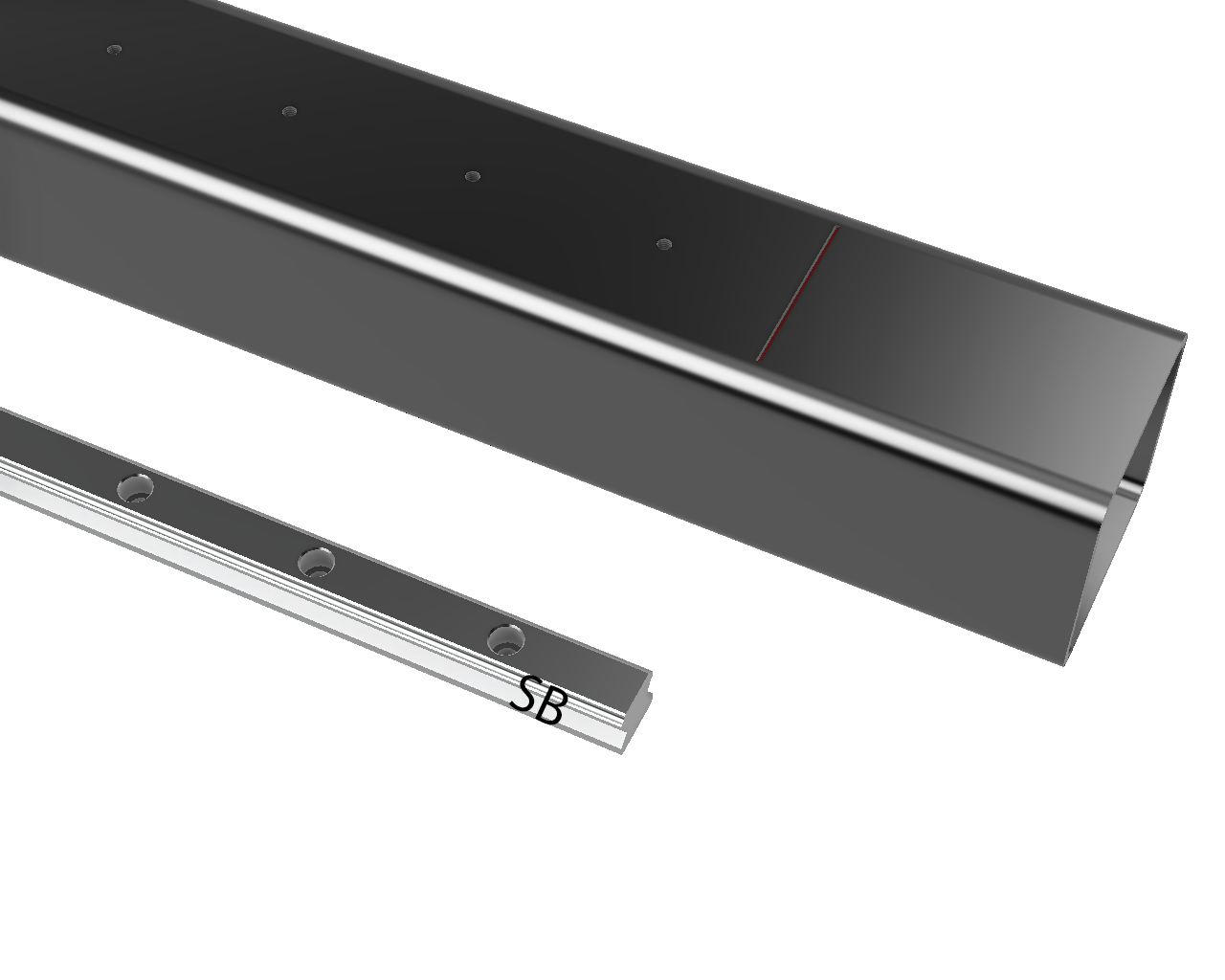
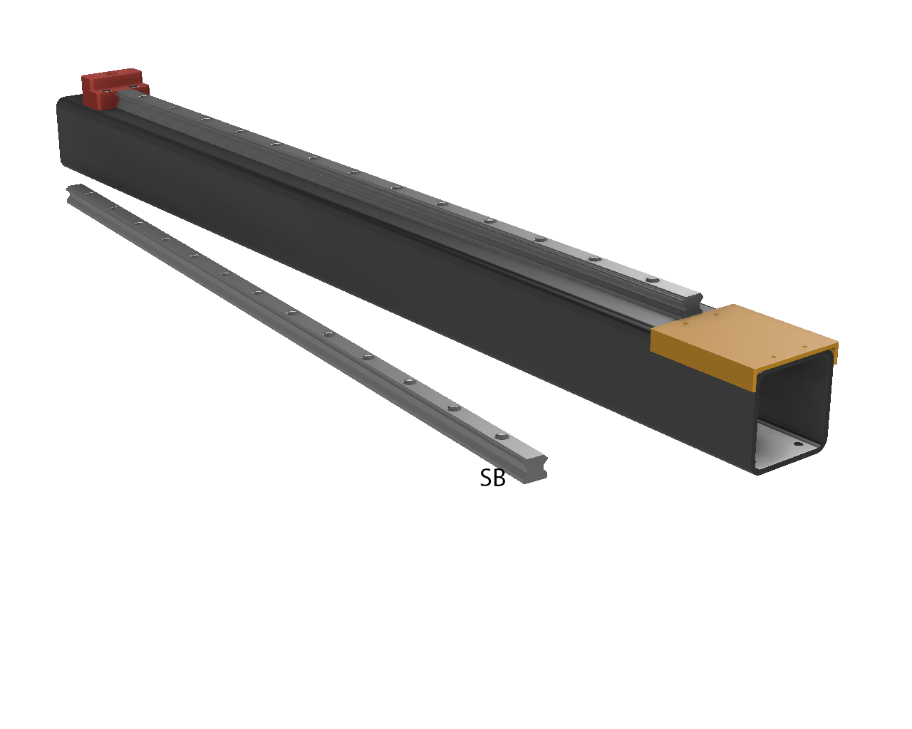
Remove the rail after marking the stepper end with SB (stepper, bottom). It’ll get attached again at a later step with the carriages installed.
 |
 |
¶ Step 6C: Gantry Bottom to YRollers
- Drill 6.5mm
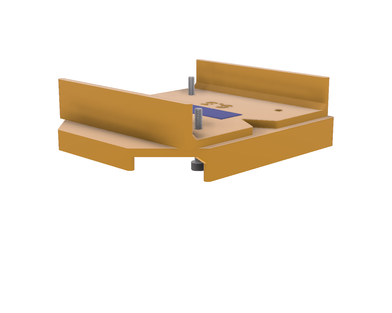
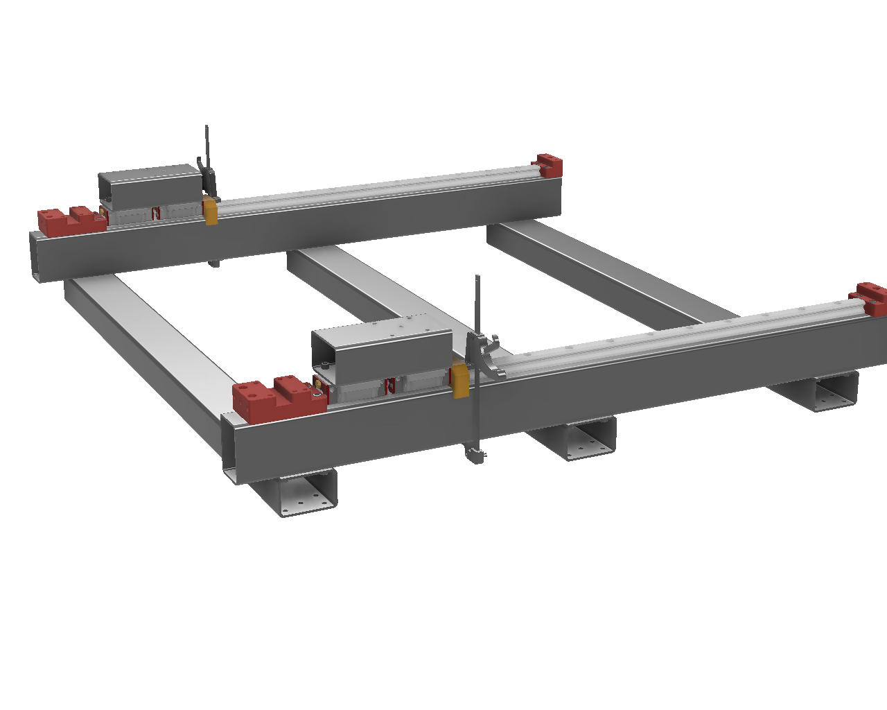
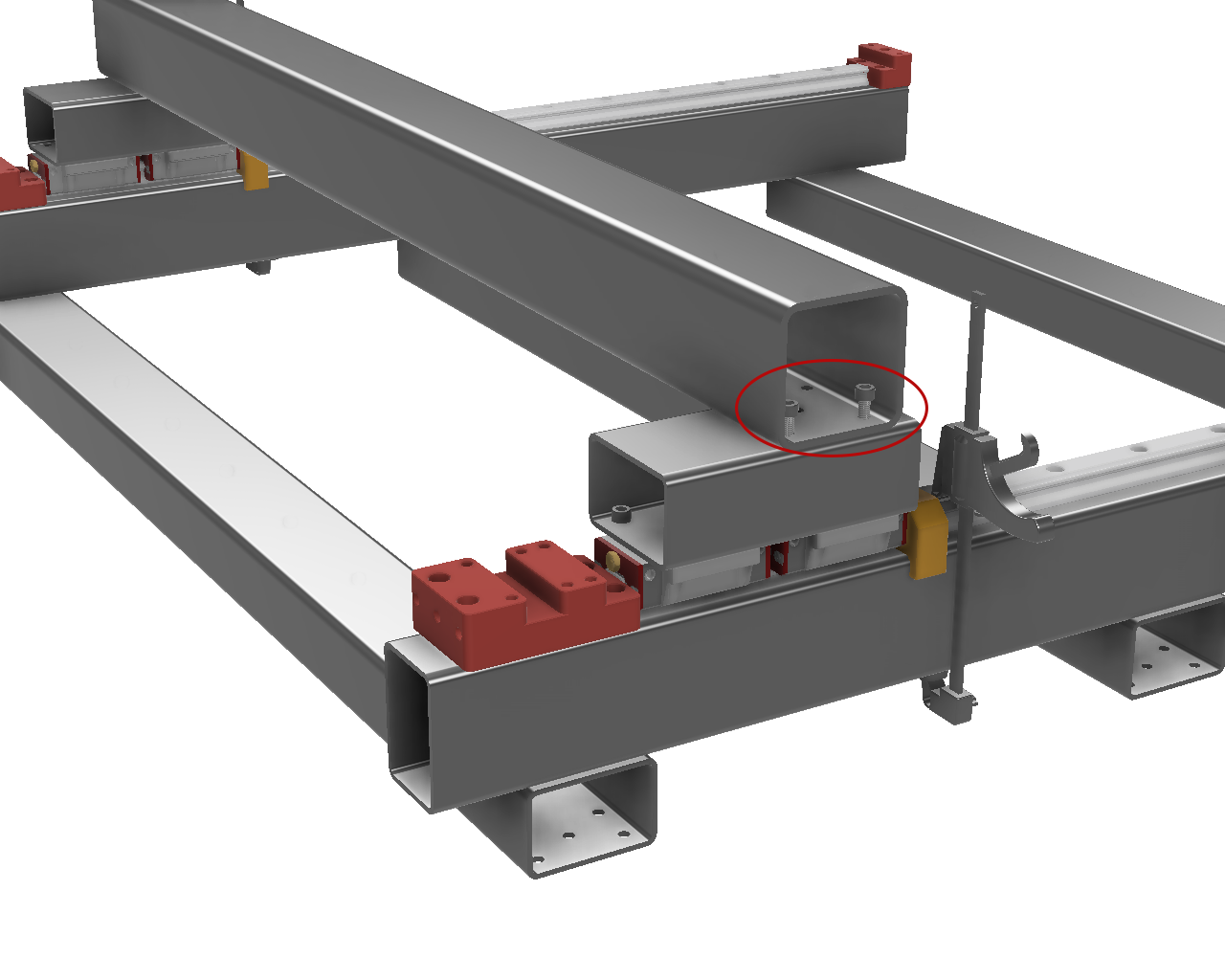
Use #6 Gantry-YRoller drill guide aligned with one end of the gantry tube. Mark and drill the holes.
If your gantry length is not equal to X-Frame Length + Y-Roller width - Y-Frame width, adjust the guide to compensate.
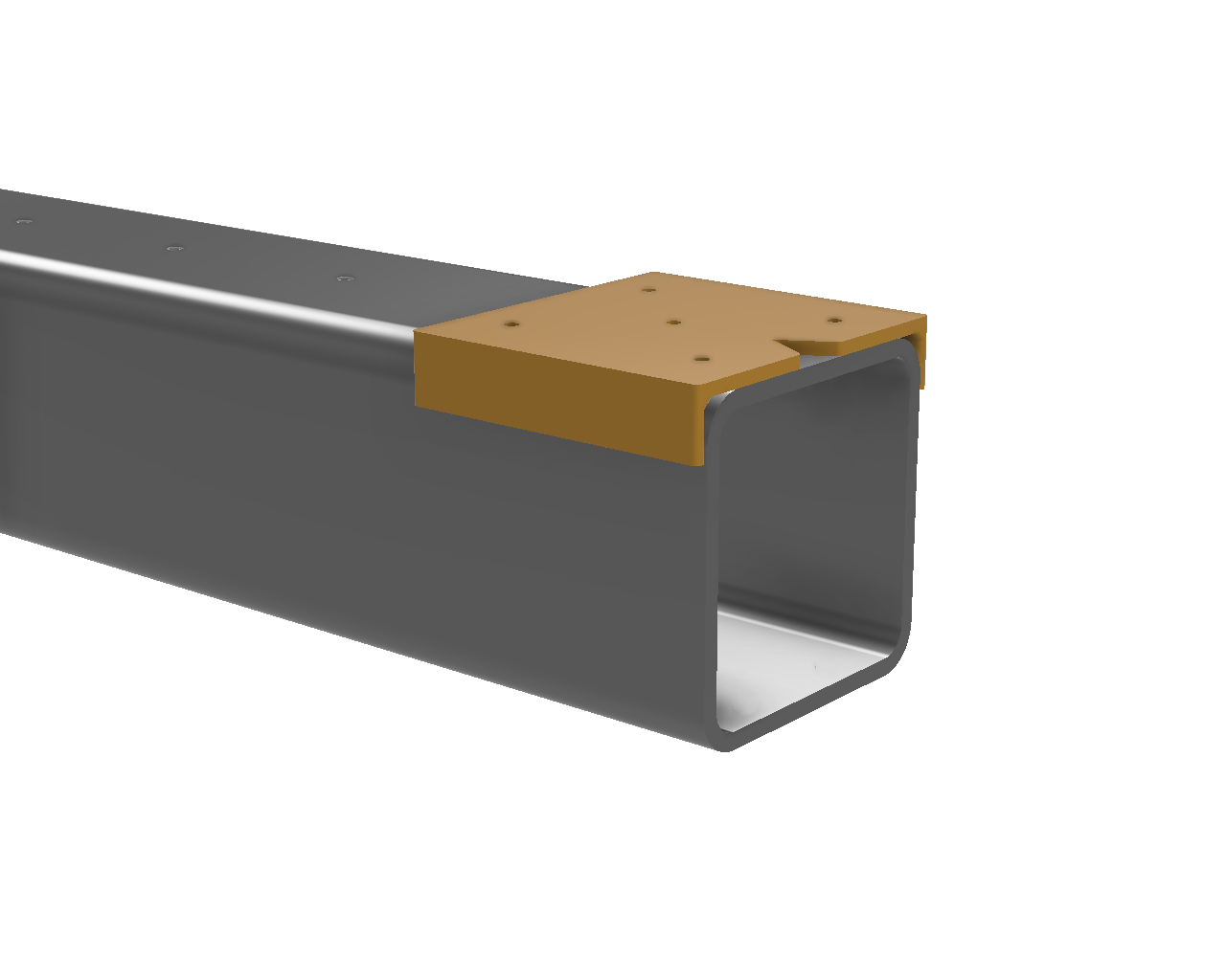
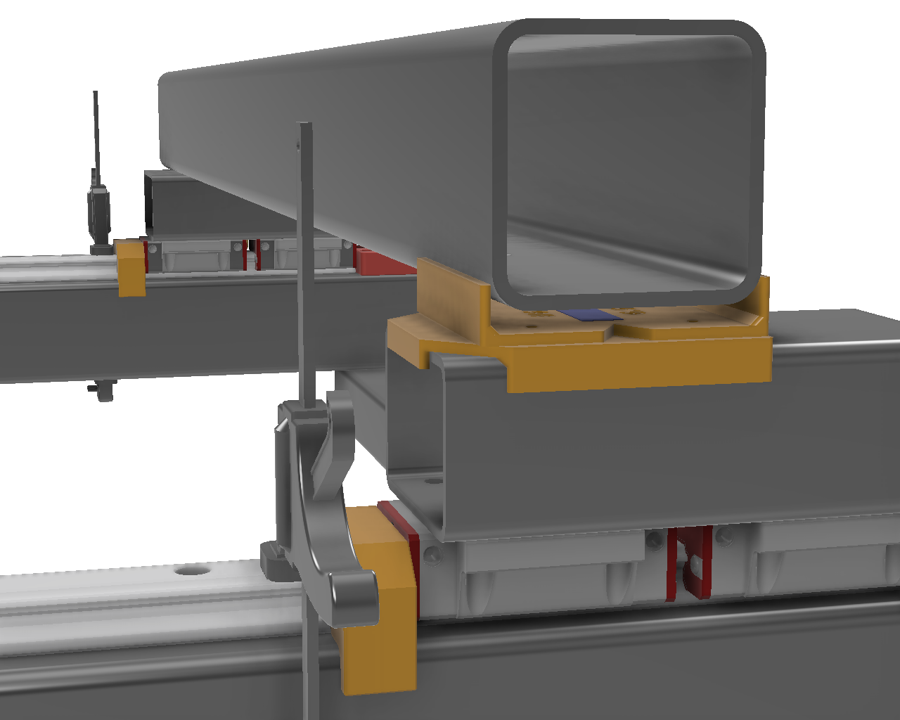
Cut a small square of two sided tape and put on both the top and bottom of the #6 Gantry-YRoller drill guide. Align the holes through the #5 YRoller-Gantry drill guide (you can put some right size bolts through the holes to make the alignment easier) and press the two guides together.
Move both carriages to the front of the machine, put the rail centering guides behind them to lock in place.
Place the gantry on the rollers and loosely install two bolts to align left-right. Lift the right side of the gantry enough to slide the combined #5-#6 drill guides between the roller and gantry, and lower the gantry onto the 2 sided tape. Remove the 2 bolts and gantry from the rollers, keeping the combined drill guides taped to the gantry.
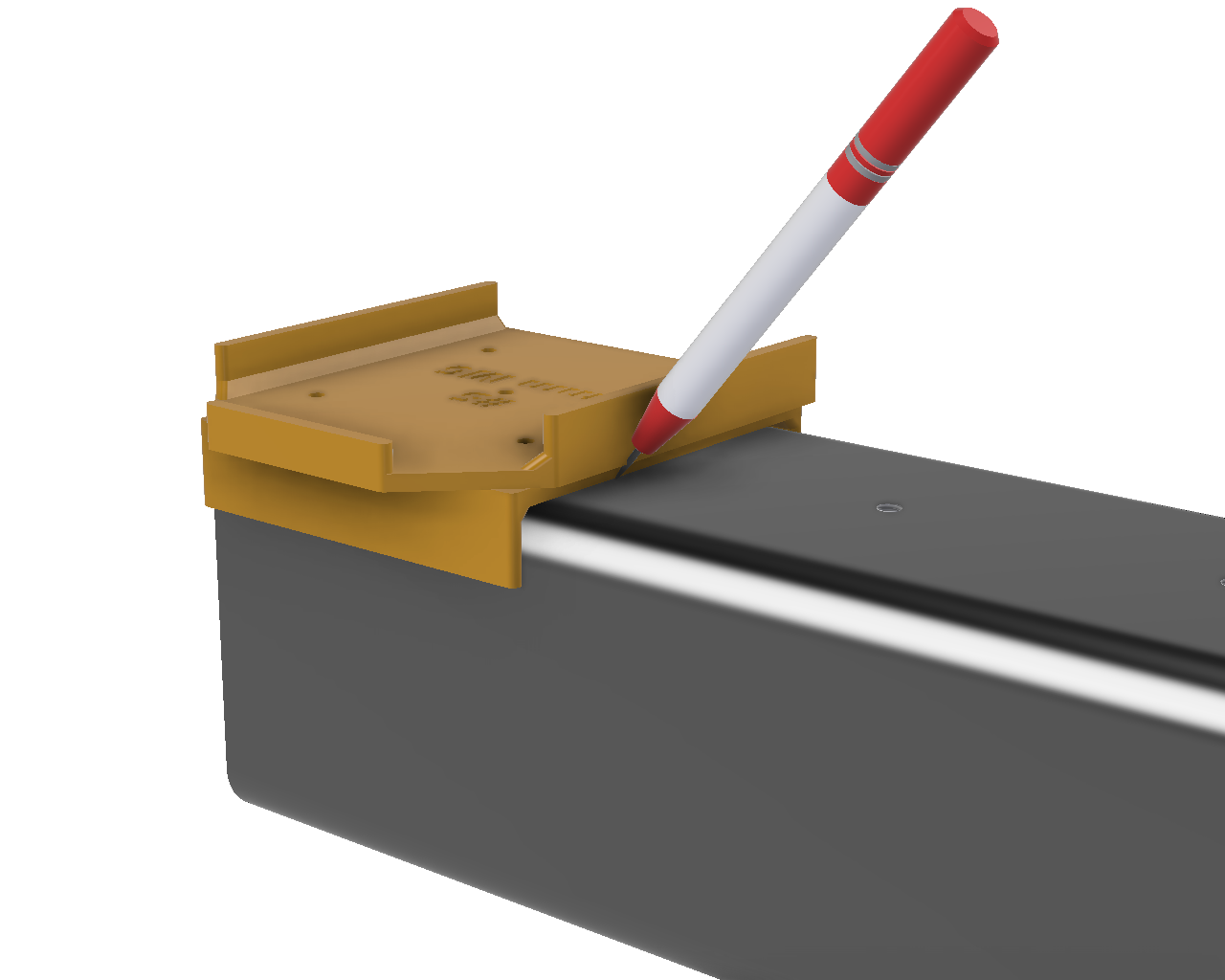
Use the scribe to mark the end of the guide, then remove both guides and two-sided tape. Then replace #6 Gantry-YRoller on the bottom of the gantry tube, mark and drill the holes.
|
|
|
|
|
|
¶ Step 7A: Gantry Top to BFBKHM Risers
- Drill 5mm, tap M6 for M6x30
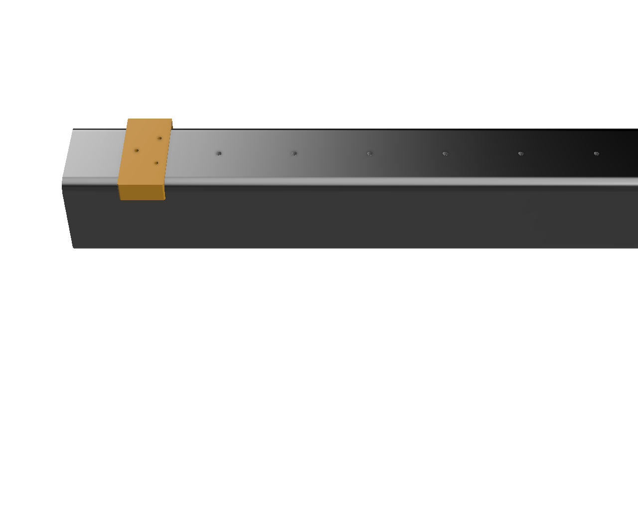
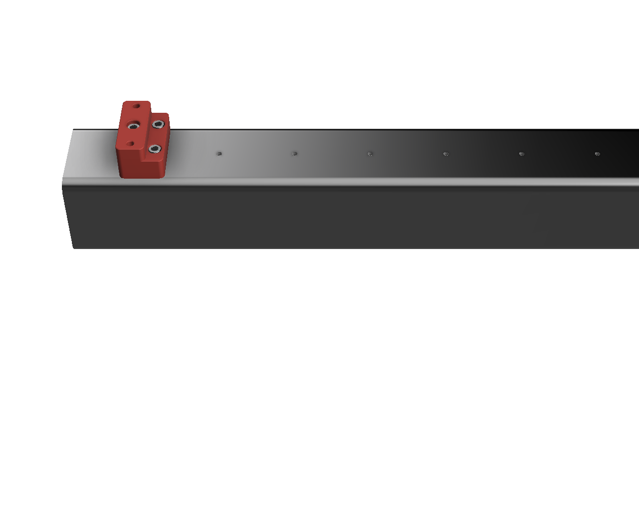
Align the #7A XGantry-BF drill guide with the single hole facing the end of the gantry and the two holes edge aligned with the first mark created in the Gantry Prep step above. Center punch and drill the holes. Install the BF Riser. Align the other X linear rail with the end of the BF riser and place the #7B XGantry-BKHM drill guide (or #3B if your gantry and YFrame steel are the same width) against the other end of the rail with a 1-2mm gap, then center punch, drill and tap the holes.
 |
 |
 |
¶ Step 7B: Gantry Top - Linear Rail
- HGR20 - Drill 4.2mm, Tap M5 for M5x20
- HGR15 - Drill 3.3mm, Tap M4
Install the BKHM and BF risers. Align the top X linear rail between the BKHM and BF risers, use the XRail Centering Guides (or reuse the YRail ones if Gantry and YFrame are the same width) and mark the first and last holes for the rail, and drill, tap and bolt the rail on before marking the rest of the holes. Remove the rail after marking the stepper end with ST then check the center punches are aligned with the centerline mark before finishing drilling and tapping the rest of the rail holes.
Install 1 or 2 carriages that have been prepared in the Carriage Preparation step above on both XTop and XBottom Linear Rails (with one zerk facing each direction if two carriages per rail) then align the linear rails facing the BKHM block with the marked end of the rail and tighten the bolts, but just tight enough that the rail doesn’t move.
Install the Gantry back on the Y rollers using 2 bolts per side.
¶ Step 7C: Gantry to Roller Brace.
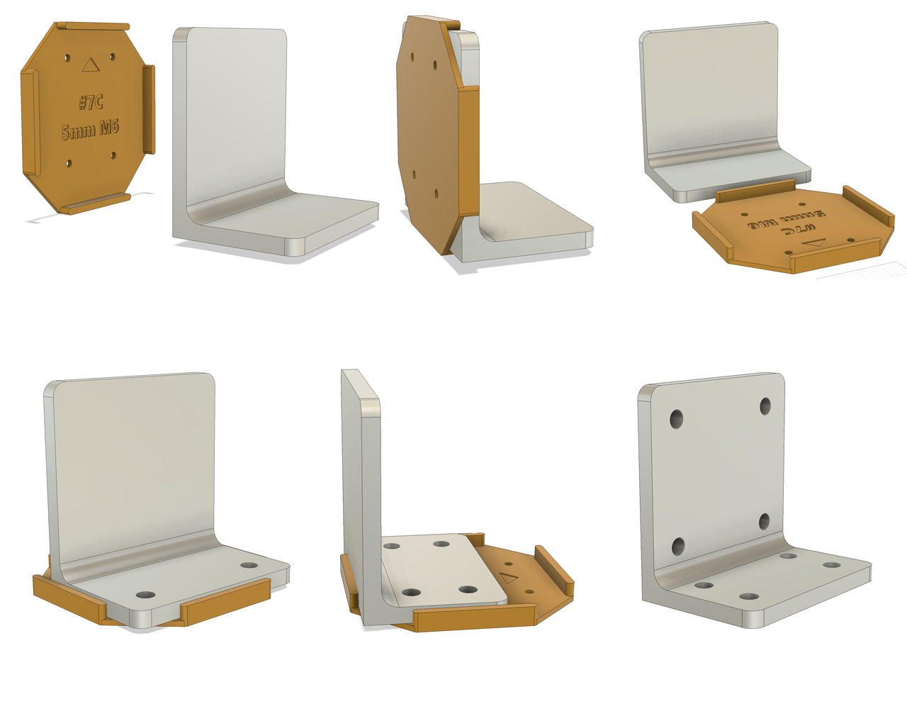
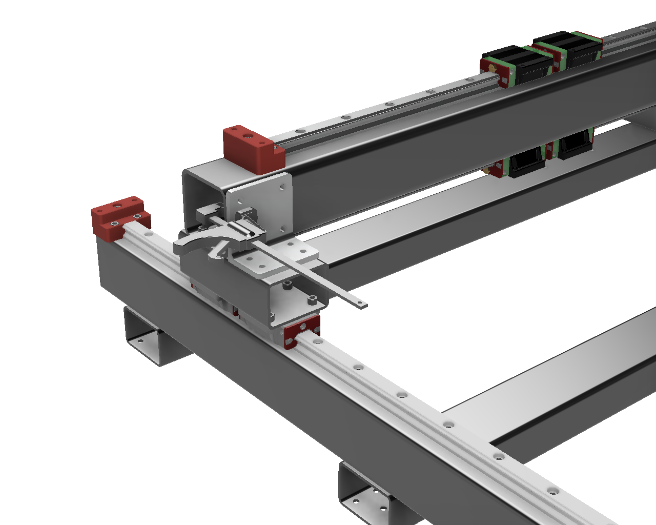
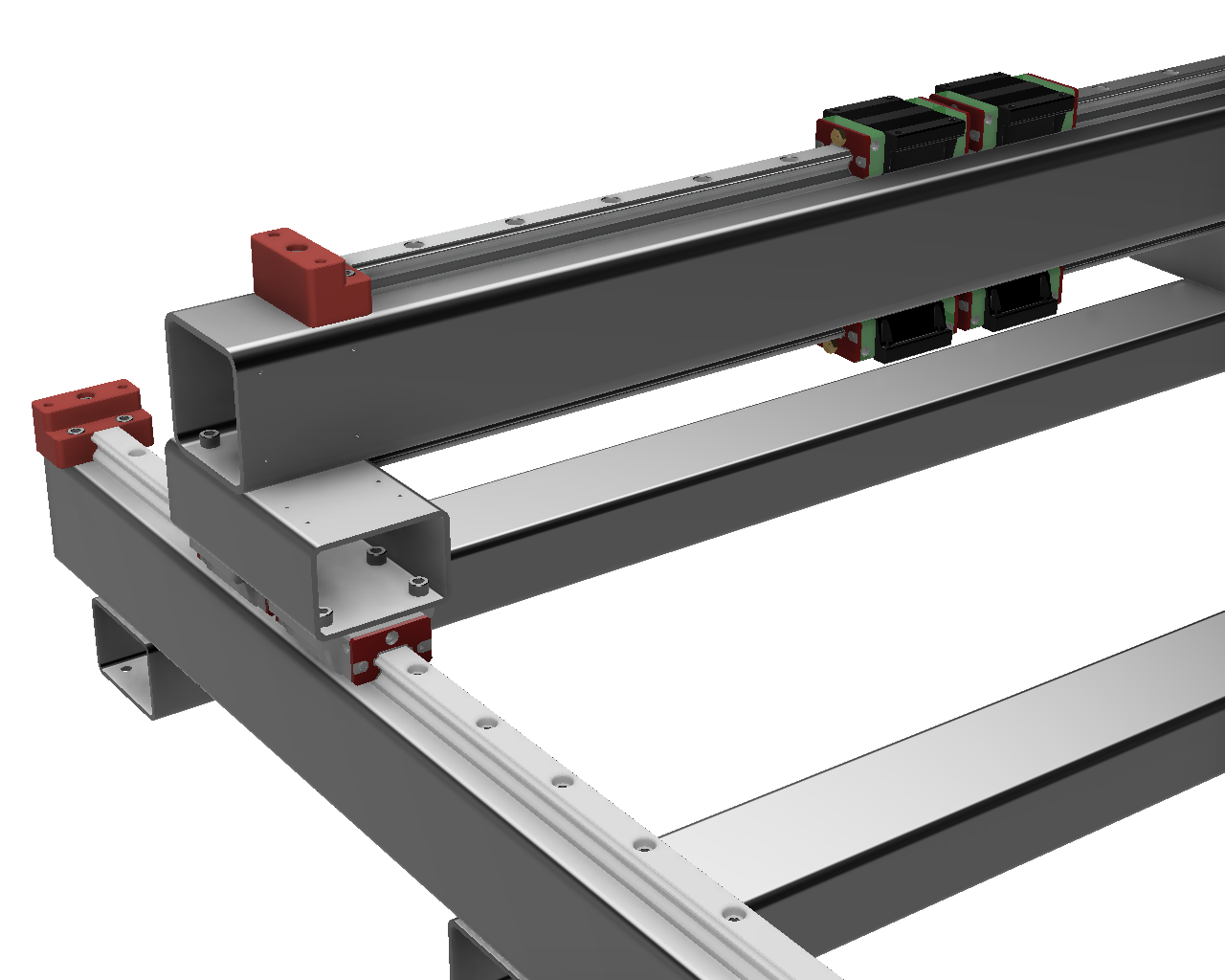
Use #7C Gantry-YRoller Brace drill guide on the back of the angle brace to center punch for the holes, arrow facing up. Then use the same guide on the bottom, arrow facing forward.
If you’re using unequal angle (50x75+), for the short side, align the angle with the arrow facing forward and the front side tight to the guide for the front holes, and the back side tight for the back holes.
Drill the angle out to 6.5mm, then place it on the Y roller and clamp to the front of the gantry while you center punch the holes into the roller and gantry. You can leave them until Step 11, then drill and tap them.
 |
 |
 |
¶ X Rollers, Chains and Sensors
¶ Step 8A: X Top Roller to Carriages
Place the #8A drill guide against one edge of the X Top Roller. Use a transfer punch to mark the 4 hole locations on the top and bottom of the roller.
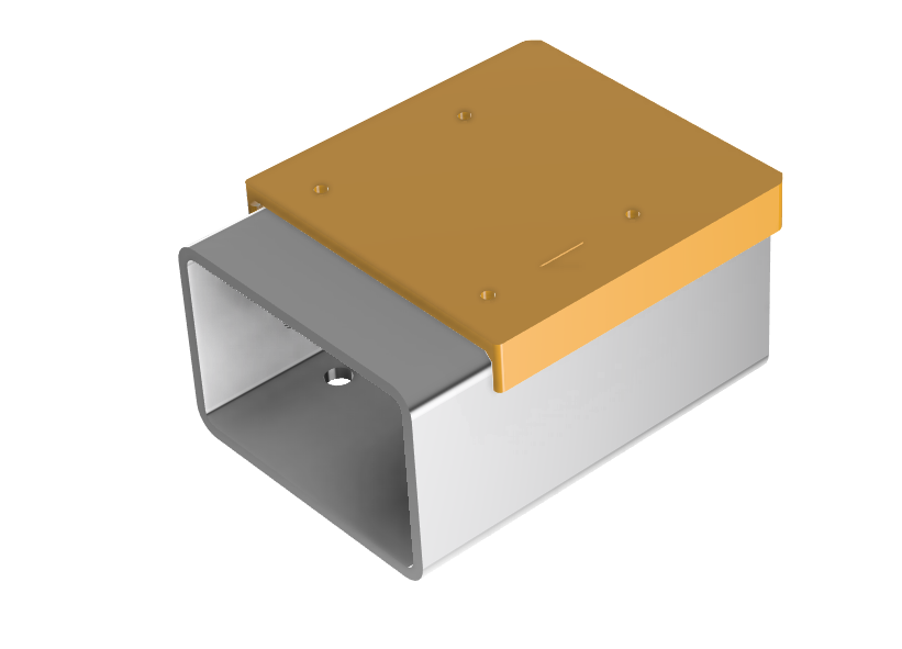
If you are using dual carriages, mark holes on both ends of the X Top Roller.
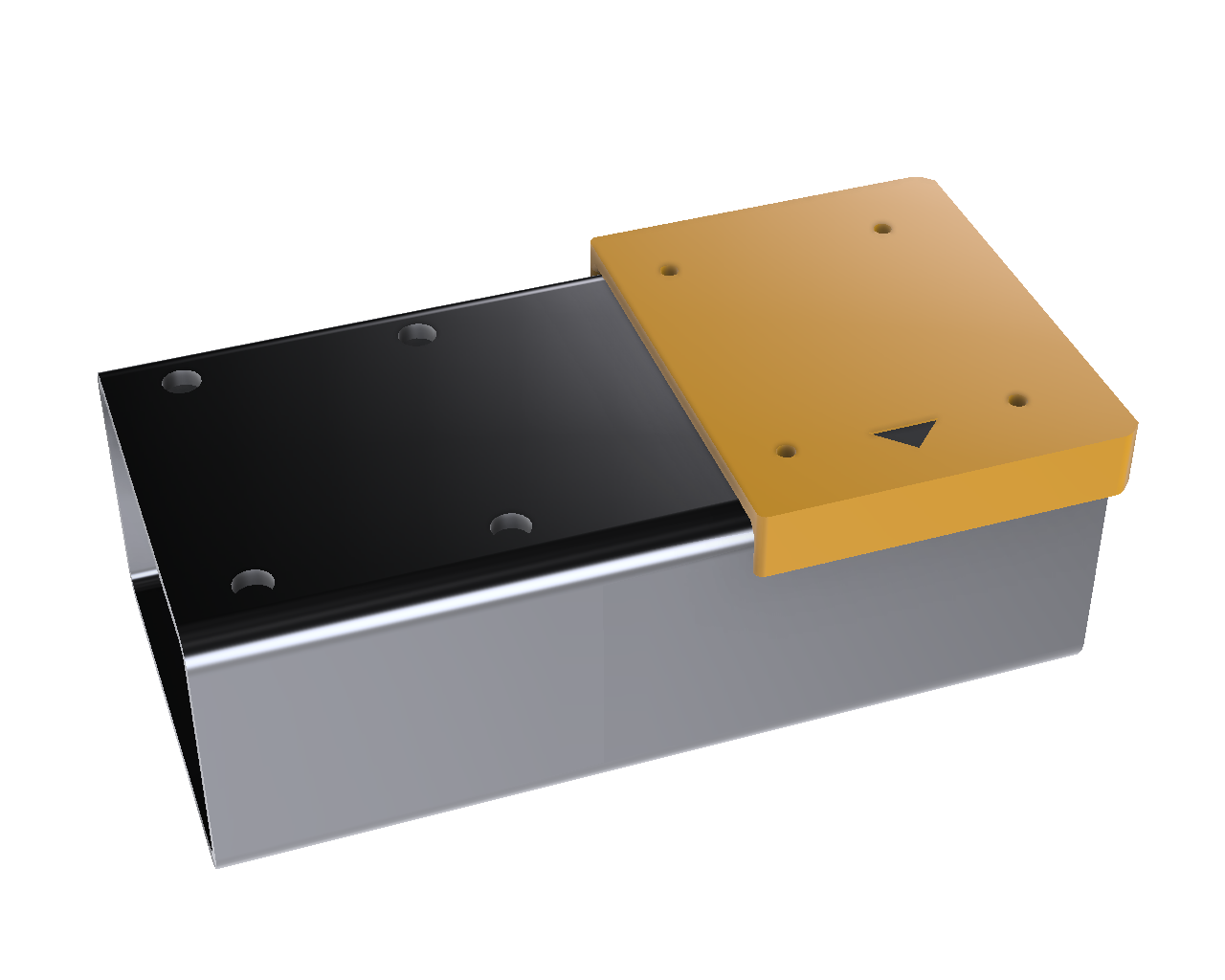
Drill the marked holes with the correct size drill bit for your carriages:
- HGH15CA carriages - Drill 4.5mm holes for M4x8 bolts
- HGW20CC carriages - Drill 6.5mm holes for M6x12 bolts
Note: If you are using 50x100 steel rollers and gantry, you can change the ‘XRoller Offset’ parameter in Fusion to move the X Top Roller toward the back of the machine. If you do, the drill guide will become double sided so that the holes are located correctly. Make sure the arrow is facing the front of the machine when marking the holes for dual carriages.
¶ Step 8B: X Top Roller to Z plate
- Drill 5mm, Tap M6
- 5x M6x12 bolts (no shim)
OR
- Drill 5mm, Tap M6
- 5x M6x20 bolts (8mm shim)
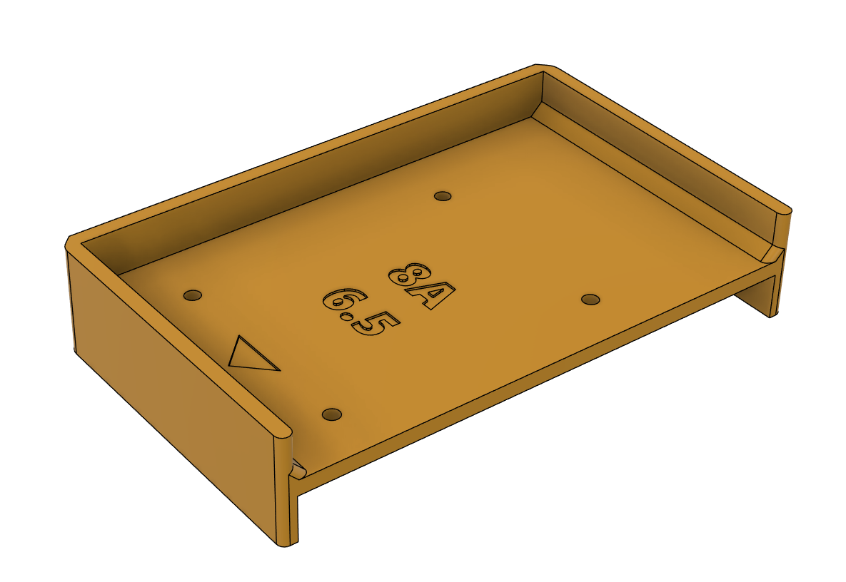
Use #8B X Top Roller-ZPlate drill guide to mark the front of the Top X Roller. Drill 5mm holes and tap them M6.
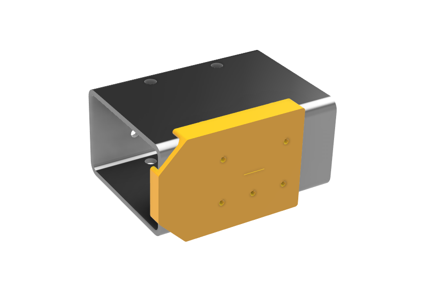
Attach the carriage[s] to the bottom of the Top X Roller using the specified bolts.
Dual carriages: Slide the X roller carriages onto a rail and make sure the roller runs smoothly. If tightening the bolts causes the carriages to twist out of alignment with each other and cause binding, clamp something straight to the sides of the carriages to align them before tightening the bolts into the carriages.
¶ Step 8C: Optional X Roller Shim Plate
- Drill 6.5mm
Measure and mark a vertical centerline on the shim plate, then align the #8B X Top Roller-Zplate drill guide center hole with the line, mark and drill the 5 holes.
¶ Step 9A: X Bottom Roller to Carriages
- HGH15CA - Drill 4.5mm
- 4-8x M4x12 bolts (optional - pancake/wafer head bolts for extra Z clearance)
OR
- HGW20CC - Drill 6.5mm
- 4-8x M6x12 bolts (optional - pancake/wafer head bolts for extra Z clearance)
Use #9A X Bottom Roller-Carriages drill guide to mark the lower angle. The arrow faces towards the front of the CNC. For dual carriages, flip the printed drill guide over and mark the other side of the angle, with the arrow facing forward for both sets of holes. Install the Top X Roller to the carriage[s] using the specified bolts after completing Step 8B. If using dual carriages, ensure the roller runs smoothly.
Dual only: if tightening the bolts causes the carriages to twist out of alignment with each other and cause binding, clamp a block to the sides of the carriages to align before tightening the bolts into the carriages.
¶ Step 9B: X Bottom Roller to Z Plate
- Drill 5mm, Tap M6
Use #9B X Bottom Roller-ZPlate drill guide to mark the forward face of the angle, with arrow facing up. Mark, drill and tap the holes.
¶ Step 10A: Install Z Plate
Aluminum ZPlate - 8x M6x12 bolts (no X Roller Shim) or 4x M6x12 and 4x M6x20 (8mm X Roller Shim)
Temporary Wood ZPlate - 8x M6x20 bolts (no X Roller Shim) or 4x M6x20 and 4x M6x30 (8mm X Roller Shim)
Align either the temporary wood Z plate or aluminum plate with the outside pairs of holes on both the top and bottom X rollers and install the above bolts. Ensure the rollers can move reasonably easily with little force and there’s no binding over the travel distance.
¶ Step 10B: Y Sensor and YRoller Cable Chain Mounts
Measure 25mm from the front and back on the outside of the Y roller on the Y cable chain side and scribe a centerline. Measure 25mm from the back of the other Y roller on the outside and scribe another centerline. Use #10A YAxis Chain and Sensor drill guide to mark 2 holes on each line, then move rollers to the back of the machine, until the dual carriages hit the printed BF riser, or until the carriage is 15mm from the BF Riser for single carriage (use the Y Rail Centering guide as a spacer), and use the center two holes in the #10A drill guide aligned to the rear set of holes on the roller to mark the holes for the trigger mount.
Optional: Mark the YMin trigger location by moving the gantry until the dual carriages hit the BKHM riser or the single carriage is 15mm from the BKHM riser (use the YRail centering guide as a spacer), align the #10A drill guide with the back set of marks on the left side of the machine and use the center pair of holes to mark the YMin trigger location.
On the Y frame on the same side as the X stepper, measure from the back and mark a center line for the Y Cable Chain mount behind or in front of the rear X Frame tubing (depending if it’s inset from the rear of the CNC frame or not), then every 300mm from the first line towards the front of the machine, adjusting as necessary to avoid the other X frame tubing by 25mm to prevent conflict. Use the bottom two holes in the #10A drill guide to mark the holes for the cable chain mounts and supports, using the centerlines.
¶ Step 10C: X Sensor and XRoller Cable Chain Mounts
Measure 25mm from the left and right side on the back of the X Top Roller and scribe a centerline. Use #10B XAxis Chain and Sensor drill guide to mark 2 holes on each line, then move the X Roller to the right side of the machine until the dual carriages hit the printed riser, or until the carriage is 15mm from the printed riser for single carriage (use the Yrail centering guide as a spacer) and use the drill guide aligned to the right set of marks on the roller (if the X Stepper is on the right side of the machine, or left holes if left side) to mark the holes for the trigger mount using the center pair of holes in the #10 drill guide.
Optional: Mark the XMin trigger location by moving the ZPlate to the left side of the machine until the dual carriages hit the printed riser or the single carriage is 15mm from the printed riser (use the YRail centering guide as a spacer), align the #10A drill guide with the same set of set of marks for above (left side for left X stepper, right side for right X stepper) and use the center pair of holes to mark the XMin trigger location.
On the X Gantry on the same side as the X stepper, measure from the end and mark a center line for the X Cable Chain 25mm past the Y roller (100mm for a 75mm roller, then every 300mm from the first line towards the other side of the machine. Use the bottom two holes in the #10B drill guide to mark the holes for the cable chain mounts and supports, using the centerlines.
¶ Step 11: Drill and Tap Holes Marked in Steps 7C, 10B, 10C
- Drill 5mm, Tap M6
Completely unassemble the frame in preparation for painting, but first find the marks created in steps 7C, 10B and 10C on the YFrame, YRollers, XFrame and X Top Roller and drill and tap for the Gantry Braces, Cable Chain Mounts and Supports, and Sensor Mounts and Triggers.
¶ Finished initial assembly? go here for painting > https://wiki.printnc.info/en/v4/painting
¶ Next Steps:
- Build the Electronics Enclosure
- Add a wasteboard
- Add limit sensors or endstops
- Add cable chain/cable management/drag chains
- Plan water cooling
- Print caps for ends of steel (optional) - You can find these in the PrintNC CAD fusion model in the outline under “Hardware” - “Caps”
- Insert caps on rails (optional) - might want to wait a couple of weeks until after tuning/calibration
- Add a dust shoe
- Add a probe
- Add an air blast
- Add a sidewall or bellows
- Do some test cuts to ensure they match the expected height, width, and depth. Also, do simple cuts/designs on different materials to validate feeds and speeds.
- Put on the PrintNC stencil