¶ Summary
Assemble the Z-axis with motor, coupler, and motor mount
¶ Prep
¶ Hardware Needed:
- Prepared frame assembly from prior section
- (1) BK10 bearing block
- (1) Aluminium milled Ballscrew nut block ("T-Nutblock") (a 3d printed one can be used as a temporary replacement- see https://wiki.printnc.info/en/v3/metal#t-nut-block for more info)
- Stepper motor coupler
- (6) M5x20 socket head screw
- (4) M6x50 socket head screw
- (1) 1204 Ballscrew with nut on the end
- (4) M5x20 socket head screws
- (6) M4x16 socket head screws
¶ Printed Parts Needed:
- Z-Axis NEMA Motor Mount (Tip: Check out the "Z Motor Mount + Inductive Switch Mount" on the https://wiki.printnc.info/en/mods page)
- Ballscrew nut block ("T-Nutblock") (for temporary use, replace with aluminum milled one)
¶ When complete, verify:
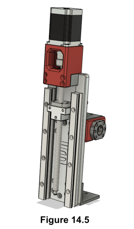
- Motor should be bolted on the Z axis
- It should look like Figure 14.5
¶ Build Steps:
- Position the BK10 bearing block on the faceplate with its protruding part faced upwards as shown in Figure 14.1.
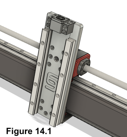
Be sure to have the BK10 bearing block in the correct orientation. The bottom of the BK10 block is flat.
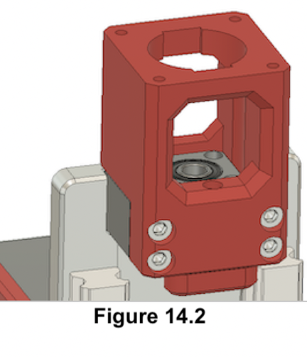
- Place the 3d printed Z-Axis NEMA Motor Mount on the BK10 and fasten both with (4) M6x50 socket head bolts as shown in Figure 14.2. Do not fasten it tight right now as it needs to be aligned in the next step.
- Wood Plate only: Use longer bolts and fasten them with a nut and washer on the backside.
-
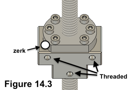
Check that your aluminum Ballscrew Nut block has (3) M5 threads and you have cut any excess material away (it should look like a "T"). See the fusion file for measurements of the Ballscrew Nut Block. See Figure 14.3 for more info.
-
Mount the Ballscrew Nut Block to the Nut with (6) M4x16 socket head screws. You may want to ensure the zerk fitting is accessible. (M6 45 or 90 zerk might be the best fitting to use.)
When using an aluminum Ballscrew Nut Block, angled zerk fittings may prevent the Ballscrew Nut from seating properly on the block - you may need to file down the zerk fitting slightly. Common 45 degree zerk fittings use a 9mm wrench to install, but the Ballscrew Nut face is only 8mm thick. (Straight zerk fittings typically use a 7mm wrench to install.)
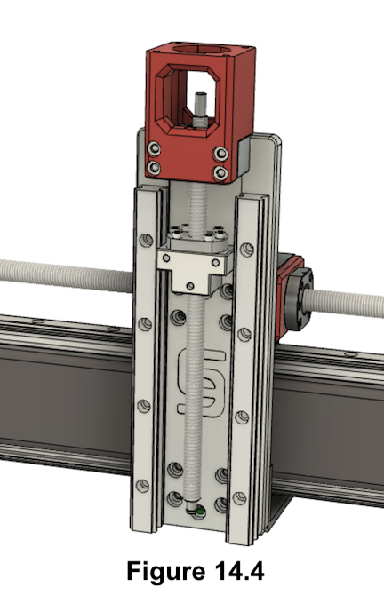
- Insert the ballscrew into the BK10 bearing and secure it with the retainer nut on the top. Tighten the retainer nut with the setscrew as shown in Figure 14.4.
-
Place the motor coupler on the top end of the ballscrew.
-
Place the motor on top of the motor mount and with its axle in the coupler.
-
Bolt the Motor to the mount with (4) M5x20 socket head screws.
-
Fasten both setscrews of the coupler. It should look something like Figure 14.5.

- You can now short-circuit your motor cables e.g. with a wago clamp so the motor has more holding force during the following steps.