¶ Summary
Assemble the X-Axis gantry
¶ Prep
¶ Hardware Needed:
- Prepared X-Axis gantry beam with HGR20 rails loosely mounted (including the X-Axis Roller Beam prepared from X-Axis_Roller_Beam_Prep step)
- Assembled frame from prior steps
- (8) M6x16 button head bolts (for attaching X gantry to Y rollers)
- (6) M6x30 bolts for printed BK12 and BF12 mounts
- (6) M6x50 bolts for attaching BK/BF to printed blocks
- Allen key / driver bit for M6 bolts
- Circlip/c-clip pliers
- (2) HGW20 carriages
- (4) M5x20 socket head bolts with nuts for mounting motor to motor mount
- (2) M6x30 socket head bolts for mounting motor mount to rail
- (1) motor
- (1) coupler
- (6) M5x130mm Threaded Rod (for the X Roller Beam assembly)
- (12) M5 nuts (one for each side of the X Roller Beam assembly)
¶ Printed Parts Needed
- Center Line Marker Tool
- (1) BF12 mount block
- (1) BK12 mount block
- (1) Ball screw face plate front
- (1) Ball screw face plate rear
- (1) Motor mount
¶ When complete, verify
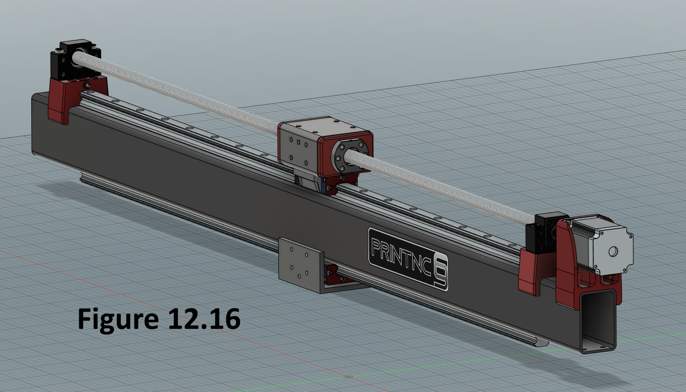
- Two carriages are on the X-axis gantry, one on top and one below. The top X roller will have three holes on the top of the front face.
- The motor is mounted with a coupler.
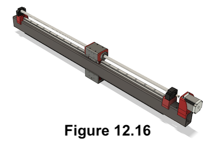
- It should look something like this:
¶ Build Steps:
-
The HGR20 rail should be lightly attached to the X-Axis gantry so that it can be wiggled without much force.
-
Add zerk fittings to (2) HGW20 carriages (side does not matter yet). Slide an HGW20 carriage on the top of the X gantry with the zerk fittings on the opposite side of the ballscrew nut. Slide an HGW20 carriage on the bottom of the X gantry with zerk fitting on same side as the top HGW20. Leave the end bolt for each end of the rails so the head sticks slightly out of the rail to keep the carriages from rolling off the end.
-
Loosen the wiper screws of each HGW20 block while on the rail, and gently roll the block along the length of the rail to allow the wiper to self align. Then tighten the wiper screws up. This will drastically improve their performance and they should now easily slide back and forth.

-
Attach the X-Axis gantry to the Y-Axis rollers using M6x16mm button head bolts on both ends. You will need to put a long allen key through the M6 threaded holes created for mounting the BK12, BF12, and X-Axis motor to access the bolts. If you cannot easily reach the bolts, you can drill access holes on top of the X gantry, opposite of the mounting holes.
-
Install the BF12 mount onto the tapped holes using M6x30mm bolts.
-
Install the BK12 mount onto the tapped holes using M6x30mm bolts.
-
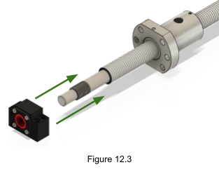
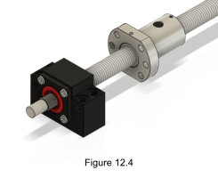
Insert a ball screw into a BK12 oriented as shown in Figures 12.3 and 12.4. You will likely need to lubricate the ball screw and the bearing inside the BK12 and gently persuade the BK12 on. Be very careful to maintain proper alignment as the low tolerances mean any mis-alignment will cause the parts to jam and sustain damaged.
-
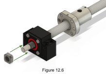
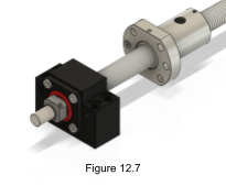
Screw the retainer nut onto the ball screw behind the BK12 as shown in Figure 12.6 and 12.7. Ensure it is securely tightened against the BK12.
-
Tighten the set screw in the retainer nut so the retainer nut can no longer move.
-
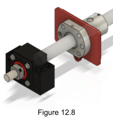
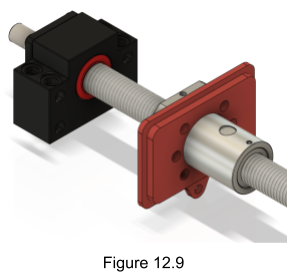
Place the Ball Screw Face Plate Front directly behind the ball screw nut as shown in Figures 12.8 and 12.9.
-
Pass the empty end of the ball screw through the top X-Axis roller beam ensuring that the three holes are on top of the front face.
-
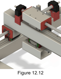
Pass the inset face of the Ball Screw Face Plate Rear over the unused side of the ball screw and slide it all the way up the screw. Insert the inset side of the printed part into the X-Axis roller beam as shown in Figure 12.12. (Note: This figure does not show the updated v3 angle on the underside of the X.)
-
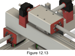
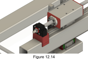
Attach the ball screw nut to the X-Axis roller assembly using M5 threaded rod, passing the bolts all the way through both printed plates. Attach M5 nuts on both ends of the threaded rod as shown in Figure 12.13 and 12.14. Only screw these nuts finger tight as they will need to be removed again. If you are using a metal ballscrew plate, you may need to shim the ball screw nut if your roller tube is not cut perpendicular.
-
Install a BF12 onto the empty end of the ball screw. Fix in place using the circlip included with the BF12 block.
NOTE: If you used PLA for the printed mounts be careful to screw the bolts in slowly so as not not cause the plastic to melt around the thread due to friction. To avoid this, you may wish to pre-thread the printed parts with a tap bit or by preinstalling an M6 bolt and removing it.
-
Install the BF12 onto the mount using M6x50mm bolts. These screw directly into the plastic.
-
Install the BK12s onto the mount using M6x50mm bolts. These screw directly into the plastic.
-
Fasten the motor mount to the rail using M6x30 socket head bolts.
-
Attach the coupler to the motor and the ball screw.
-
Fasten the motor to the motor mount using M5x20 socket head bolts with nuts. It should look something like Figure 12.16.
