¶ Summary
Create the Rollers which connect the the Z axis to the X-Gantry
¶ Prep
¶ Hardware Needed:
- center punch
- drill
- 5 mm Drill bit
- 6.5 mm Drill bit
- 7.5mm Drill bit OR 20mm Step Drill bit
- M6 Tap bit
- (1) X-Axis roller beam - 90 mm
- Angle plate - 100 mm (see https://wiki.printnc.info/en/v3/metal for more info)
- (2) HGW20 (linear bearing carriages)
- (8) M6x12mm Button Head Bolts (for mounting HGW20)
¶ Printed Parts Needed
- Assembly Tool #7 - X Axis Roller
- Assembly Tool #8 - Z-Angle Lower (if you're making the Z-angle plate)
- Assembly Tool #9 - Z-Angle Front (if you're making the Z-angle plate)
- Assembly Tool #10 - X Roller Front
¶ When complete, verify
You have prepared the upper and lower rollers for the x-axis
¶ Build Steps:
Tip: You might want to consider adding mounting holes holes to the back face of the X-roller for mounting the cable chain. This is also an opportunity to add holes to the top of the X-roller for a proximity sensor.
Components for both cable chain and proximity sensor mounting can be found here.
- Linear rail blocks ship from factory with just rust prevention oil on them. Before using them you will need to prepare them for use and lube them correctly:
1.1. Verifying blocks have clean guide edges - free from any debris or manufactoring leftovers.
1.2. Lubricating them correctly - follow your manufacturer instructions on how to deep clean your linear rail blocks and apply lube. If your blocks have a lube port, you can choose to skip deep cleaning and instead just use a lube gun to force the oil out and apply lube.
Video on how to Tune Up Linear Bearings before usage.
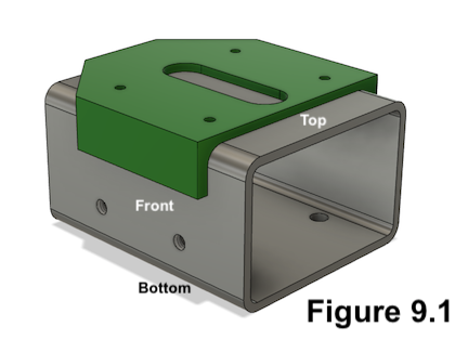
2. (Optional) For later recognition, mark at least one of the large faces as top or bottom on the X-Axis roller beam (the 90 mm sized steel) as shown in Figure 9.1.
3. Position Assembly Tool #7 on the top face of the top X-Axis roller beam with the number on the printed part facing the beam and all tabs securely holding position as shown in Figure 9.1.
4. Mark all four holes with a center punch.
5. Position Assembly Tool #7 on the bottom face of the X-Axis roller beam with the number on the printed part facing the beam and all tabs securely holding position.
6. Mark all four holes with a center punch.
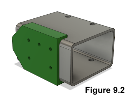
7. Position Assembly Tool #10 on the front face of the X-Axis roller beam with the number on the printed part facing the beam, the left tab all of the way on the left edge and all tabs securely holding position as shown in Figure 9.2. (Note: The hole pattern depends on the gantry height. The image shows the hole pattern for 75mm or 80mm gantry height. For a 100mm gantry, the center hole will sit in the lower row)
8. Mark all five holes with a center punch.
9. Drill the marked points on the top face with a 6.5 mm drill bit. You should have created (4) 6.5 mm holes in total in this step.
10. Drill the marked points bottom face with a 6.5 mm drill bit. You should have created (4) 6.5 mm holes in total in this step.
11. Drill the marked points on the side face with a 5 mm drill bit. You should have created (5) 5 mm holes in total in this step.
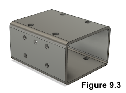
12. Thread the (5) 5 mm holes on the side face with an M6 tap bit. You should now have something that looks like Figure 9.3.
13. Position Assembly Tool #8 ont the bottom face of the aluminium Angle, aligned on its left side (left in its final mounted position) as in Figure 9.10.
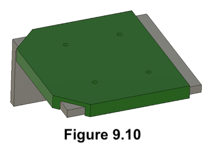
14. Mark all (4) holes with a center punch.
15. Position Assembly Tool #9 on the front face of the aluminium Angle, aligned on its left side (left in its final mounted position) as in Figure 9.8.
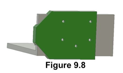
16. Mark all (5) holes with a center punch.
17. Drill the (4) holes in the bottom of the angle with a 7.5 mm drill bit OR 8mm on the step drill bit.
18. Drill the (5) holes in the front of the angle with a 5 mm drill bit.
19. Tap all (5) holes in the front of the angle with a M6 tapping bit.
20. Cut a notch for easier access of the grease fitting. You can use the step drill bit for this as well, then cut in from the edge with a grinder or hacksaw. This can be either on the left or the right side, as in Figure 9.9.
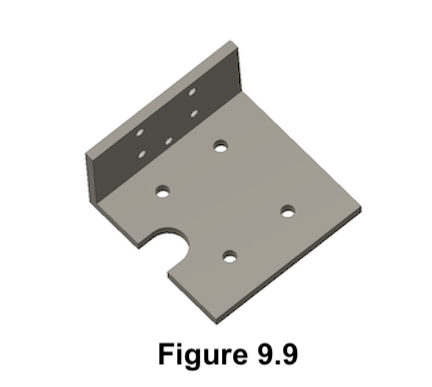
21. Add Zerk fittings to both HGW20 blocks.
22. Loosely mount a HGW20 block to the bottom face of the Z-Axis roller beam using the M6x20mm button head bolts.
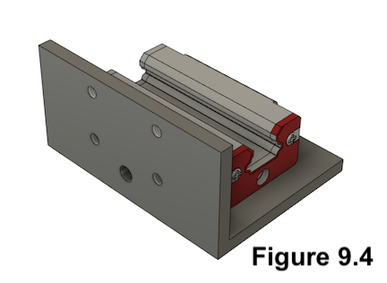
23. Loosely mount a HGW20 block to the top of the angle plate using the M6x20mm button head bolts. You should have something that looks like Figure 9.4.
