¶ Important terms
Before jumping into trying to setup your first toolpaths you should familiarize yourself with a few important terms and acronyms which are essentially the parameters you'll have to configure for each cut:
- Spindle speed [rpm]
The number of rotations your spindle will do in one minute. - Cutting speed / Vc / SFM [m/min, sf/min]
The speed at which the cutting edge of your endmill moves because of the rotation of the spindle. Different materials or cutters require different cutting speeds. This is dependent on your cutter radius and spindle speed. - Feed / Vf [mm/min]:
The speed at which the center of your endmill moves through the material. This is only controlled by your stepper or servo motors and not the spindle. - Feed per tooth / chip load / Fz [mm/tooth]:
This indicates the chip thickness each flute removes per rotation. - Depth of cut / DOC [mm]:
The depth at which the endmill moves through the material. - Width of cut / stepover / WOC [mm, %]:
The with of the cut as seen from above. This is also sometimes denoted in percent of the cutter. So a 50% WOC for a 6mm endmill means 3mm of the cutter is engaged with the material.
An absolutely great guide for further reading an be found here.
You can also use feeds & speeds calculators like FSWizard to make your life a lot easier.
¶ Getting started with milling aluminum
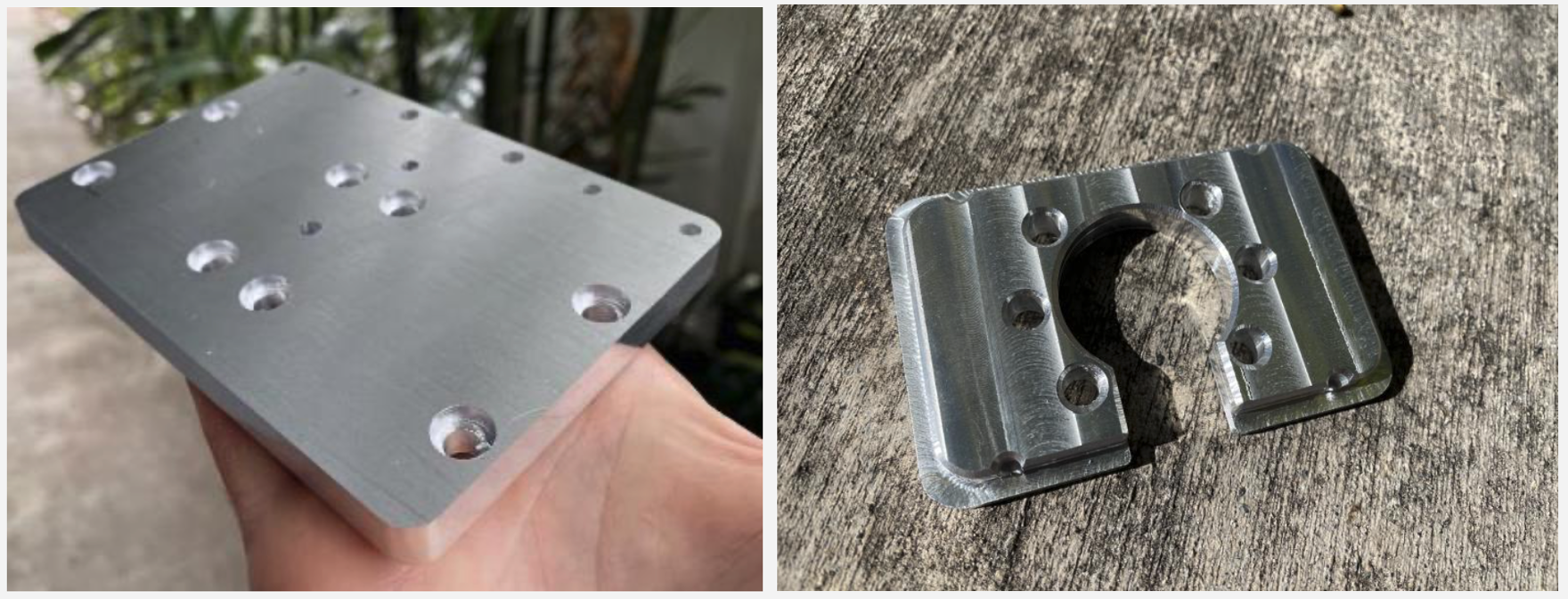
This short guide is intended for beginners willing to mill their first aluminum parts with the PrintNC. Using Fusion 360 CAM, we will go through the steps required to mill a narrow Z tramming plate and a ball screw faceplate (Logan’s design: LINK to file) from a 12mm thick 6010 aluminum stock. The bits as well as feeds and speeds selected are by no mean 100% optimum, yet they will give you relatively good results under decent run time, while keeping the bits and parts cool. Note, that a vacuum was used at all time to remove chips and prevent packing/re-cutting.
¶ A. Preparation
¶ 1) Bits selection
As stated above, single flute bits are by far the easiest for starting with milling aluminum, as they provide great chip evacuation. If possible, buy tools with diameters equal their shank diameter, so paths deeper than flute length can be used (good for boring holes). Optional 3 or 4 flute bits can be used for a cleaning and facing paths. Note that with chip thinning, the chip loads listed below are in reality most likely thinner. You may increase CPT values by 25-50% if encounter issues during milling.
|
Tool material |
Vendor |
# of flutes |
tool diam (mm) |
Shank diam (mm) |
SFM, Vc (m/min) |
CPT, Fz (mm/tooth) |
RPM (/min) |
Feed, Vf (mm/min) |
|
Carbide |
1 |
3.175 |
3.175 |
180 |
0.05 |
18048 |
902 |
|
|
Carbide |
1 |
6 |
6 |
300 |
0.05 |
15918 |
796 |
|
|
Carbide |
3 |
10 |
10 |
376 |
0.077 |
12000 |
2800 |
¶ 2. Stock attachment
Many methods exist to hold you stock in place during machining, such as clamps, vises or simply bolting down the piece directly into the waste-board with wood screws. For large stocks, like 12”’x12” Al plates, another simple method is to attach blue tape to both the backside of the plate and the waste-board (pre-cleaned) and bond the two with super glue. However with this technique, it is highly recommended to machine holes of the part first and then bolt screws through them for extra hold.
¶ B. Z tramming plate
¶ 1) Setting up the job in F360 CAM
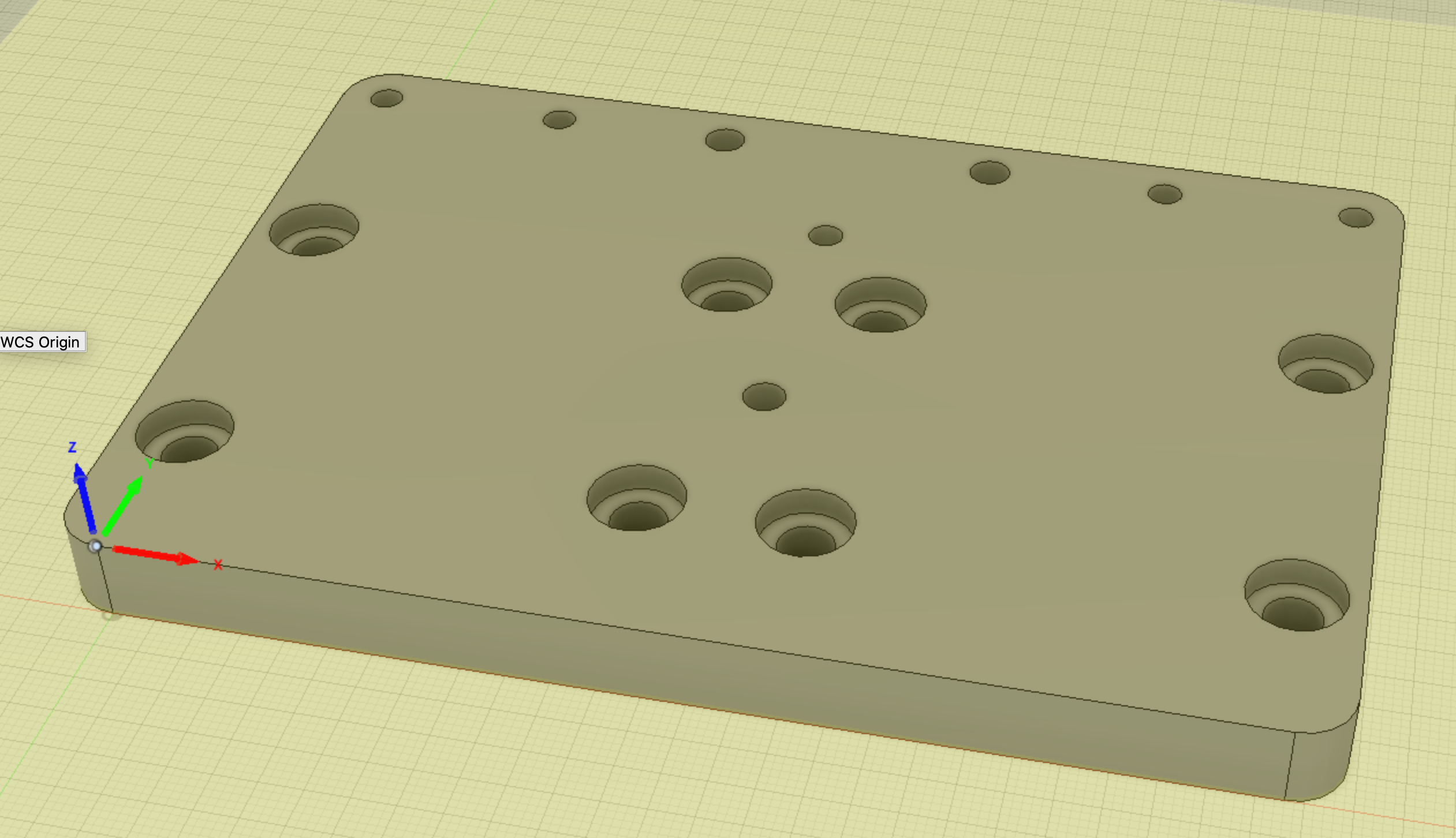
Define your stock at least 7mm larger and wider than your part. This will be important when setting up the adaptive clearing. Select your reference point for WCS as you prefer. All CAM presented below were done using the left corner at the top of of the stock as WCS origin.
¶ 2) 2D adaptive (3.175mm 1F bit)
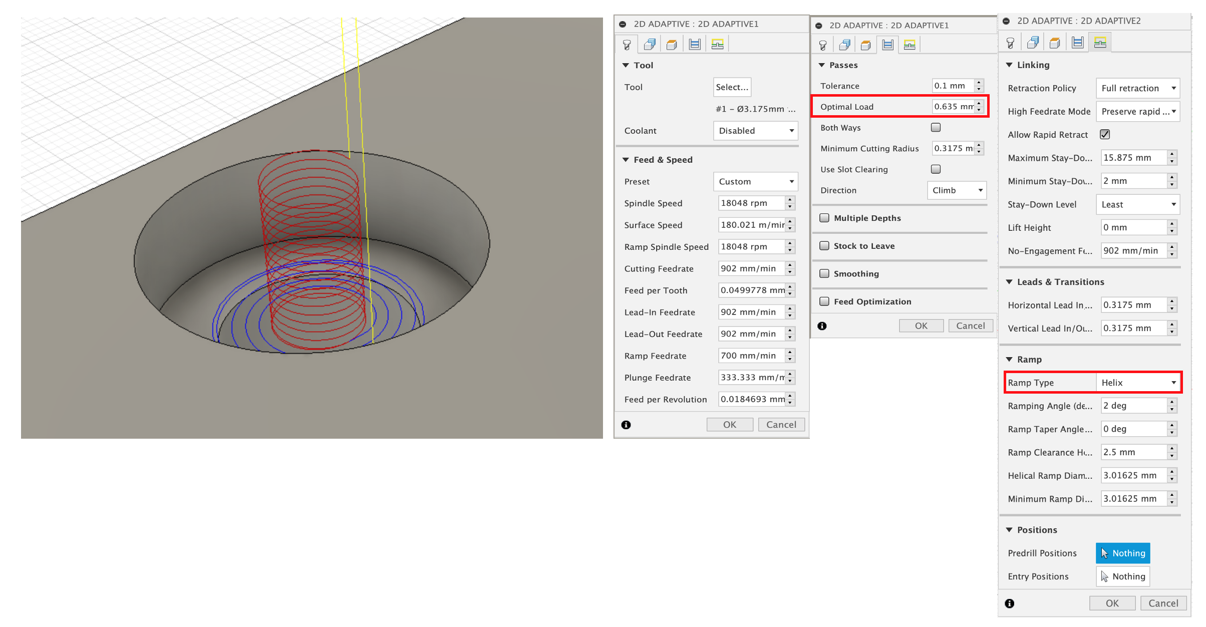
First, we cut the 8 head screw pockets using a 2D adaptive. In this operation, the bit will helix all the way down to the bottom of the pocket and then clear the rest of it. One key parameter to set is the optimal load, which is essentially the width of cut (WOC). F360 sets this value automatically at 40% of the tool diameter, which is quite aggressive. Use 20% instead. You can either enter the value (0.67mm) yourself or better edit the formula such that future 2D adaptive operations will always use 20% instead of 40% for all bits. For this right click on the box, edit expression, change 0.4 to 0.2, click OK and then right click again and select make all default such that the edit is saved for future jobs.
¶ 3) Boring (3.175mm 1F bit)
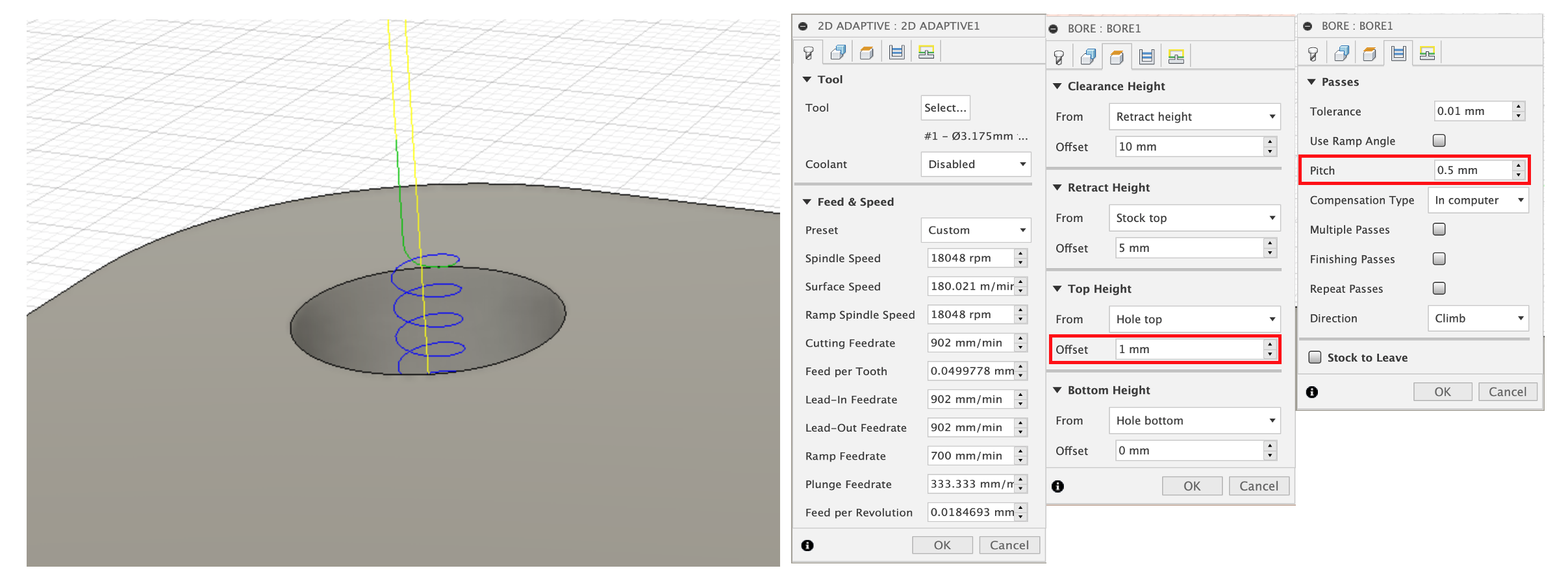
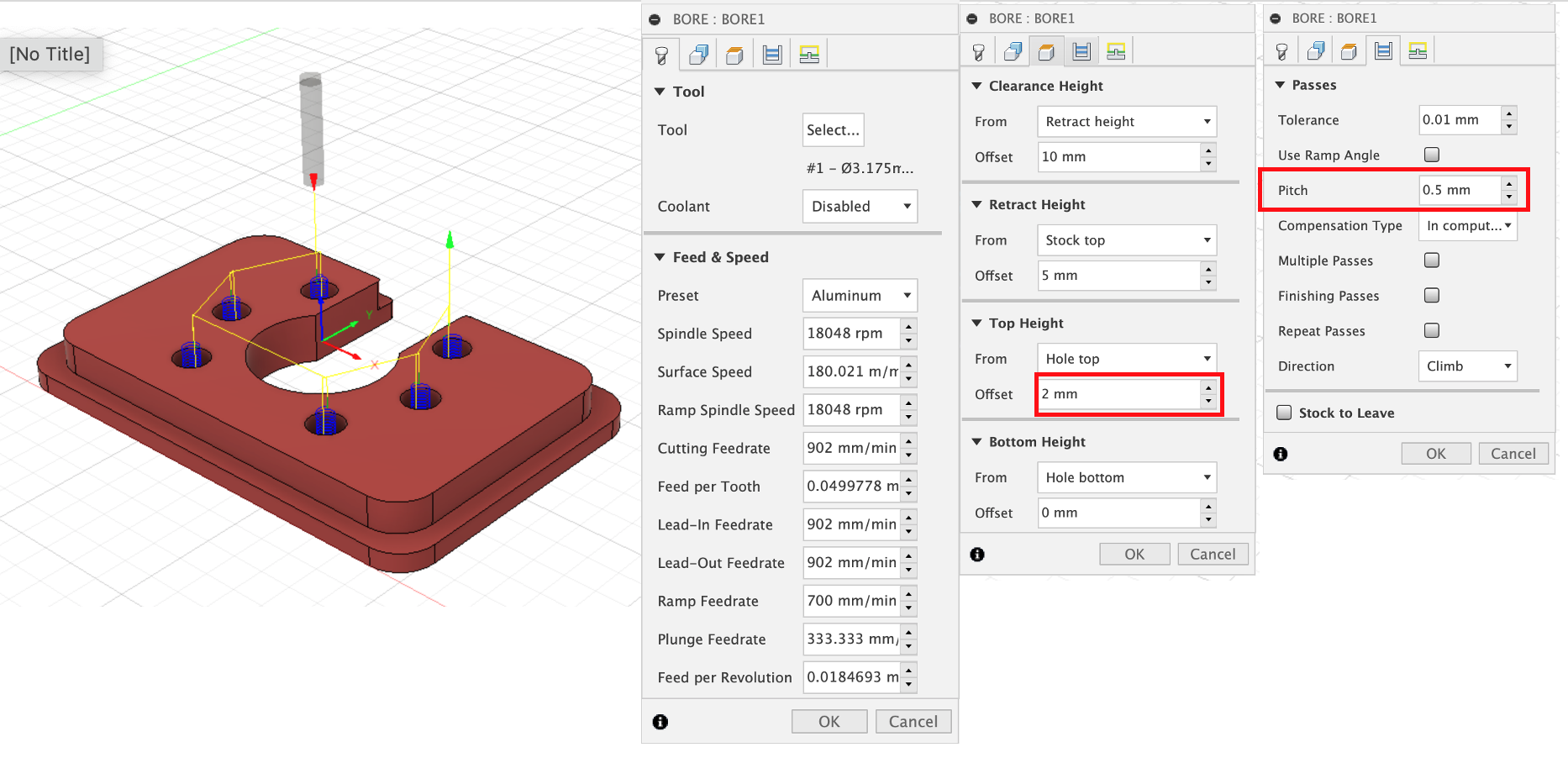
The 3.175mm bit is small enough to bore all 16 holes. By default, the helix starts right at the top of the stock. To prevent any rough entry, add 1 or 2mm offset to top height. Also reduce the pitch from 1mm (default) to 0.5mm. Once this part is done, it is now time to insert few screws into your part. This way can get away with not using tabs to hold the part to the stock.
¶ 4) 3D Adaptive clearing (6mm 1F bit)
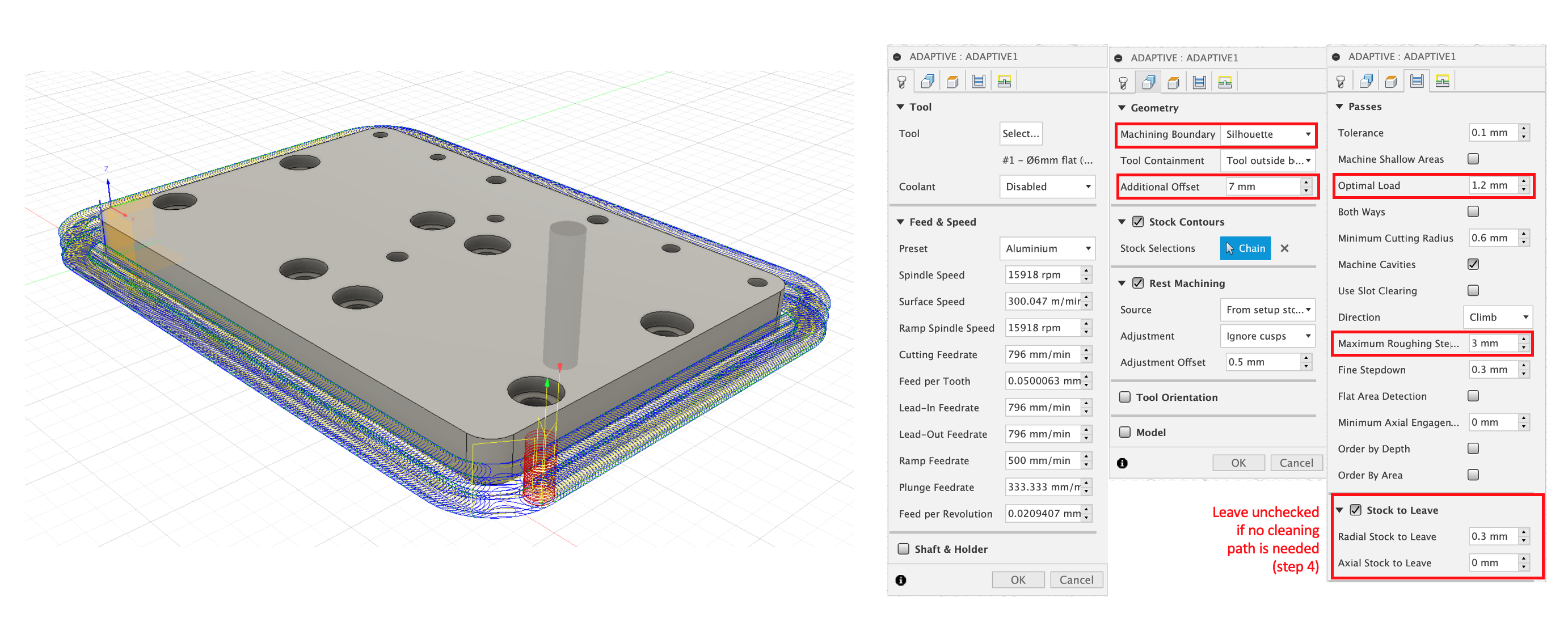
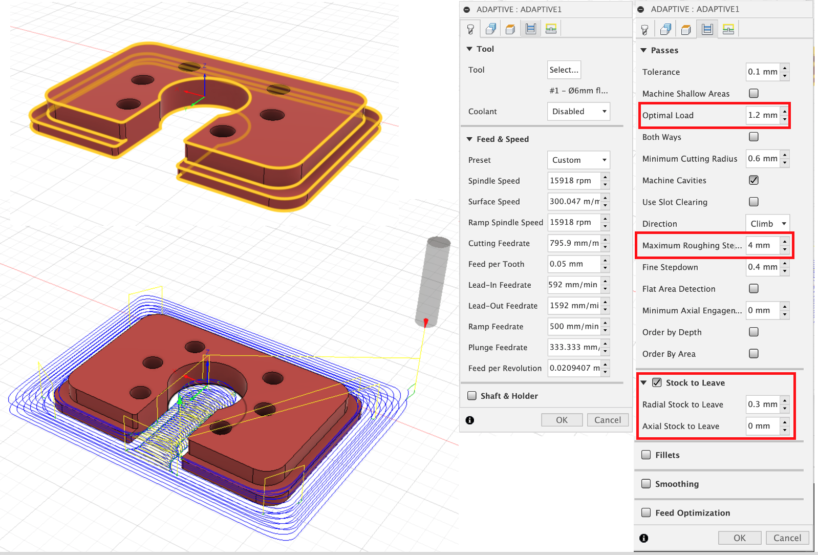
Rather than slotting aluminum, it is preferable to use an adaptive clearing, where a predefined amount of material (optimal load) is removed at all time. This step will remove material around the part perimeter, and is by far the longest step (40-60 minutes based on depth of cut, DOC). To prevent the adaptive clearing to remove then entire stock, select silhouette as machine boundary and add an offset (e.g. 7mm) greater than the tool diameter (6mm). Edit your optimal load (1.2mm) as 20% of the tool diameter. Repeat the edit steps as described above if you wish the 20% load to be applied to all bits in future 3D adaptives. It is recommended to perform this adaptive clearing in multiple paths (although it is possible with optimum tuning to mill the entire thickness of the stock at once). For now, use 3mm as maximum roughing stepdown and experiment with higher DOC once all the temporary PrintNC parts made of wood (e.g. Z tramming plates) are replaced with aluminum. Finally, you may choose to leave a little bit of stock during this step and finish the part with an optional single 2D contour. If so, leave about 0.3mm radial and 0 axial.
¶ 5) 2D contour (optional, 10mm 3F bit)
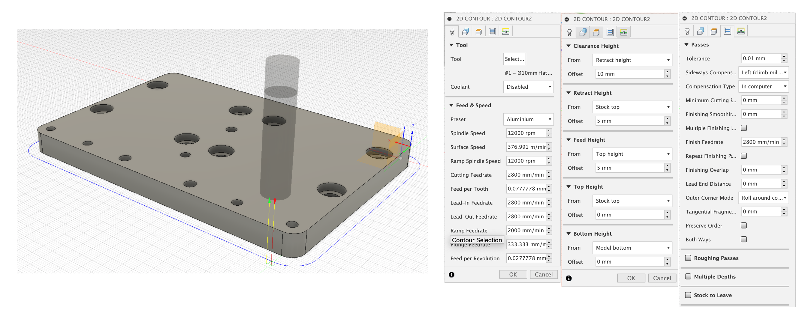
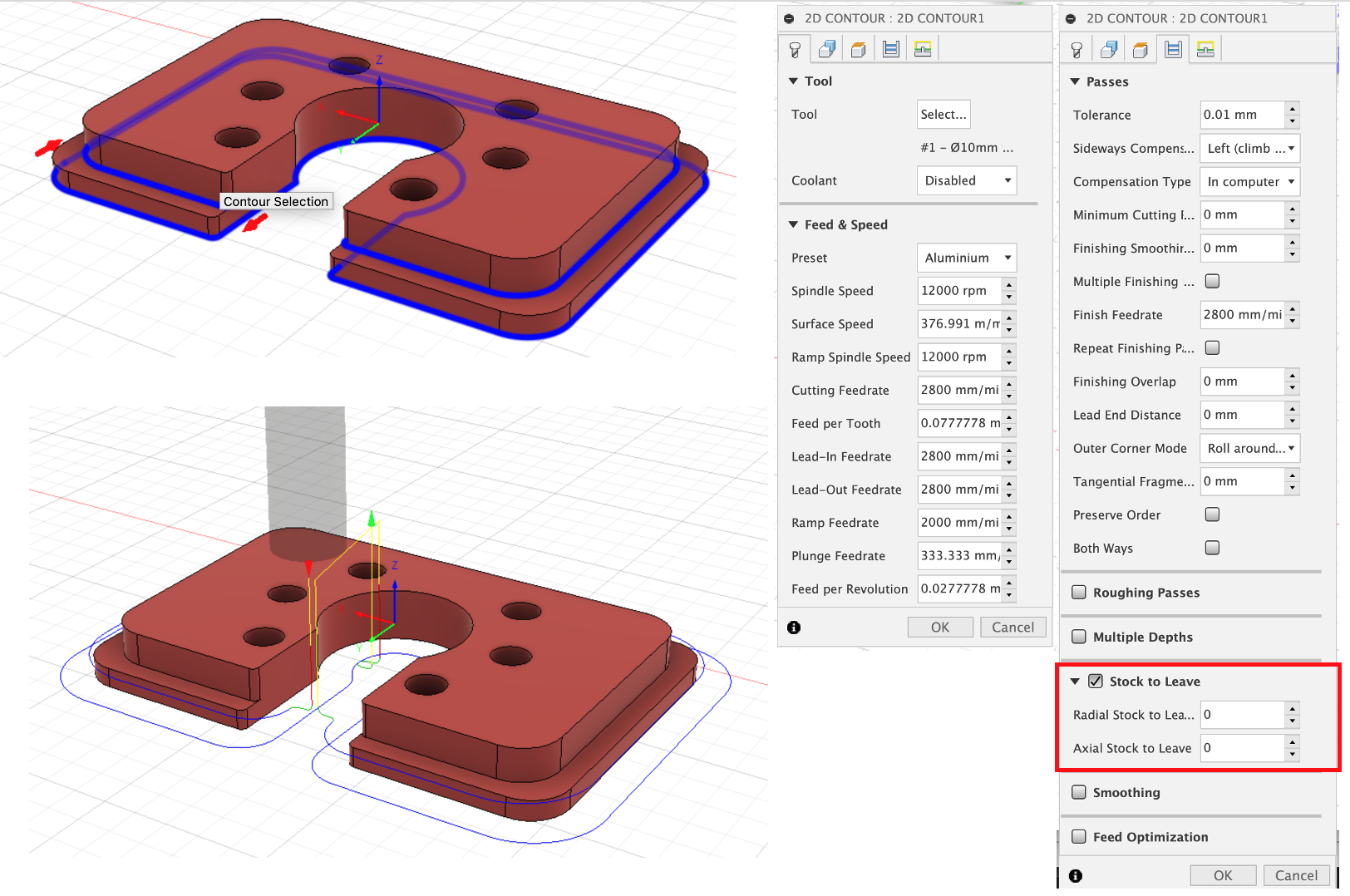
Using a 3 flute bit, perform a 2D contour to remove the excess material left during the adaptive clearing (only if stock to leave is checked). At this step, it is a good idea to experiment and remove only 0.1mm at the time and see what sort of finish is achieved after each path. Based on the quality of the bit used during the 3D adaptive step, you may find that only 0.2mm is necessary. With rougher bits, higher values maybe needed.
¶ C. Ball screw faceplate
¶ 1. Setting up the job F360 CAM
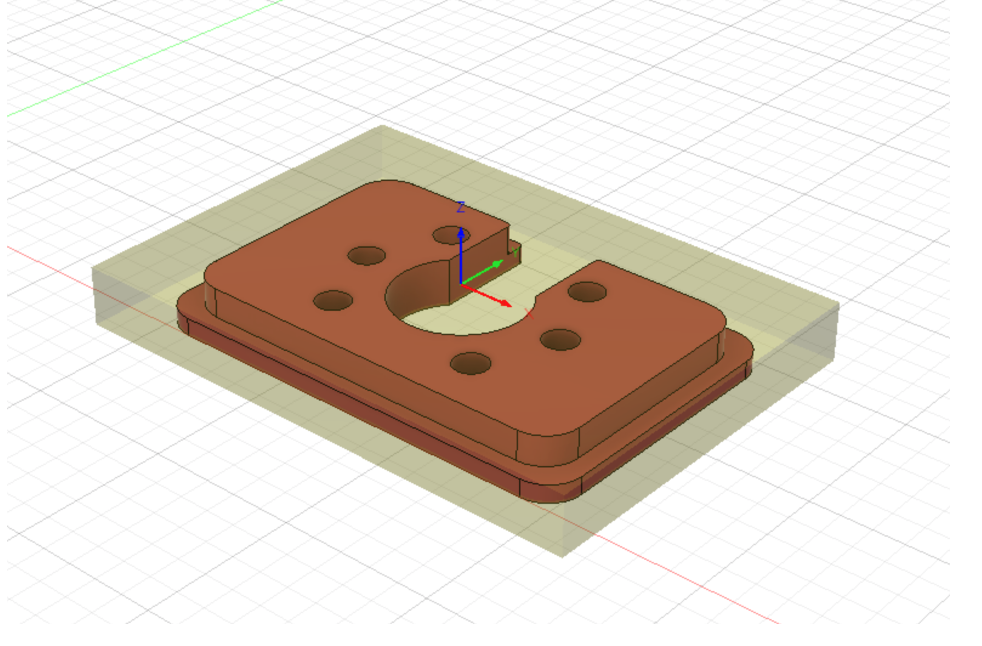
Set your stock at least 7mm larger and wider than your part. This will be important when setting up the adaptive clearing. Enter the thickness of your stock. Select your reference point for WCS as you prefer. All CAM presented below were done using the top center of the stock as WCS origin.
¶ 2. Facing (optional, 10mm 3F bit)
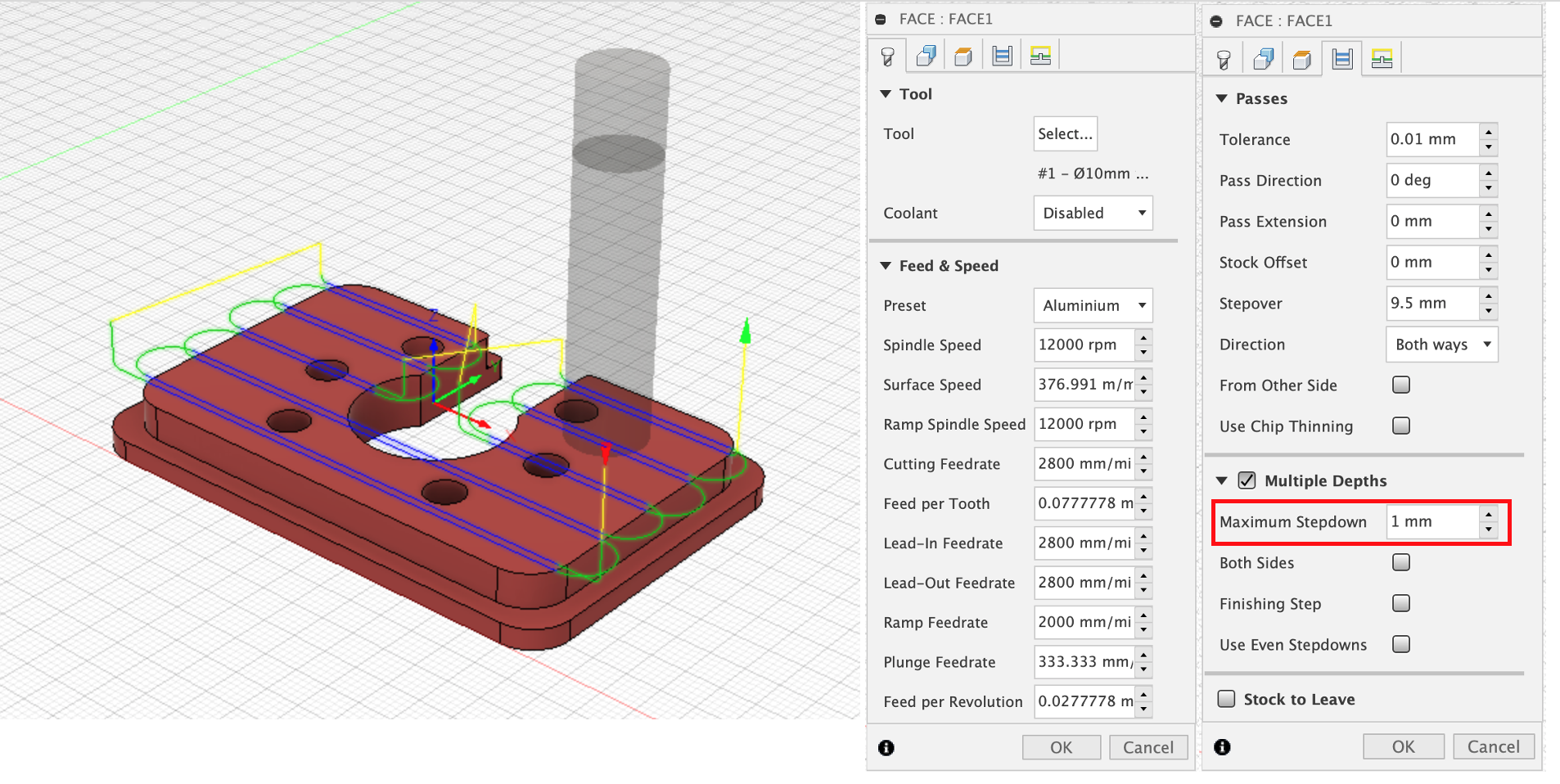
Although not necessary, you may choose to face your Alu plate down to the original faceplate thickness (8mm). Using the Face operation, mil the thickness down using a 10mm 3F carbide endmill, 1mm at the time.
¶ 3. Boring (3.175mm 1F bit)
The 3.175mm is small enough to bore all 6 holes. By default, the helix starts right at the top of the stock. To prevent any rough entry, add 1 or 2mm offset to top height. Also reduce the pitch from 1mm (default) to 0.5mm. Once this part is done, insert few screws into your part.
¶ 4. 3D Adaptive clearing (6mm 1F bit)
We will use one 3D adaptive operation to machine both the narrow and wide parts of the plate. Select the top, mid and lower profiles of the part as contours. Edit your optimal load (1.2mm) to 20% of the tool diameter. To minimize the number of paths, use 4mm as maximum roughing stepdown. You may reduce this value to 3mm (or even 2mm) first to make sure that the cutting operation is fine and push it for the next plates. Finally, you may choose to leave a little bit of stock during this step and finish the part with an optional single 2D contour. If so, leave about 0.3mm radial and 0 axial.
¶ 5. 2D contour (optional, 10mm 3F bit)
Using the 3-flute bit, perform a 2D contour to remove the excess material left during the adaptive clearing (only if stock to leave is checked). If possible, test fit the faceplate with a small section of tubing (with the faceplate still attached to the waste board). If too tight, repeat the 2D contour using a negative “radial stock to leave” (e.g. -0.1mm). The faceplate is meant to self-align, so a small gap (0.3-0.5mm) is better than a tight fit.
Note: When changing from a printed roller plate to a metal one, you may need to shim the ball screw nut if you roller is not cut perpendicular.
¶ Some guidelines from the Discord
Width of cut (WOC): always 90% of tool diameter
Depth of Cut (DOC): adjust according to chatter. For aluminum 0.5mm is low 2mm is high
Feed rate: Feed fast is good. 3500mm/min in aluminum smaller tools progressively smaller. (8mm tool 3500mm/min, 6mm 3500-2000mm/min, 4mm 2000-1200mm/min)
Spindle speed: whatever sounds and feels good. 20k rpm on single flutes spindle should sound good when spinning in the air while jogging. 20340 most of the time. larger 2-3 flutes i go lower down to 12000rpm as a minimum.
¶ Further Reading
Micro Milling: Tips for Smaller CNC Projects