¶ Summary
Assemble the screw section of the Z-axis and mount the spindle
¶ Prep
¶ Hardware Needed:
- Prepared build from prior section
- (1) Tram plate, either alu or simplified wood version for bootstrapping
- (1) Spindle clamp, with drilled holes
- (2) HGW20 Block
- (11) M6x12 socket head screws for carriages and center pivot
- (3) M5x16 bolts for tramming plate to the T-Nutblock
- (8) M5x20 bolts for spindle bracket tramming and tramming pieces
- (4) M6x40 bolts for spindle bracket mount to tramming plate
- (1) #608 skateboard bearing. (A drilled out M8 or 5/16" nut will also work.)
- (1) 8mm circlip for end of ballscrew.
- Allen key to tighten rails, and bolts
- Drill
- Drill bits for making holes for spindle mount
¶ Printed Parts Needed
- (2) Spindle Tram Pieces
¶ When complete, verify:
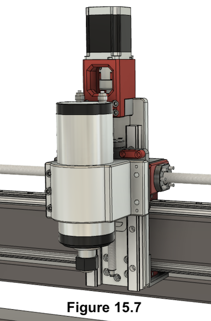
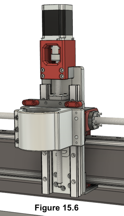
- It should look like Figure 15.7
¶ Build Steps:
- Linear rail blocks ship from factory with just rust prevention oil on them. Before using them you will need to prepare them for use and lube them correctly:
- 1.1. Verifying blocks have clean guide edges - free from any debris or manufactoring leftovers.
- 1.2. Lubricating them correctly - follow your manufacturer instructions on how to deep clean your linear rail blocks and apply lube. If your blocks have a lube port, you can choose to skip deep cleaning and instead just use a lube gun to force the oil out and apply lube.
Video on how to Tune Up Linear Bearings before usage.
-
Attach the zerk fittings to the (2) HGW20 carriage blocks. Either side is fine as they are symmetrical.
-
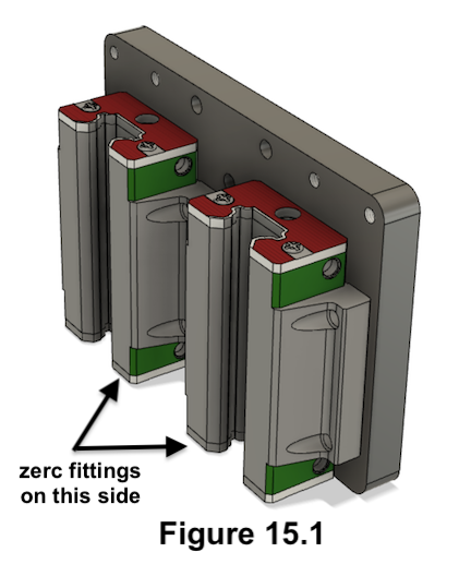
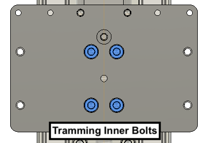
Bolt the carriages loosely with the inner (4) M6x12 socket head screws to the tram plate to connect them as shown in the "Tramming Inner Bolts" figure below. The zerk fittings should be facing downwards as indicated in Figure 15.1.
-
Loosen the wiper screws of each HGW20 block while on the rail.
-
Slide the carriages onto the rails. Be sure to not let them go until the next step.
-
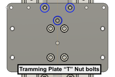
Bolt the tramming plate loosely to the T-Nutblock with (3) M5x16.
WARNING The lower center screw will have to be shortened to about 9mm or it will collide with the ball screw nut.
-
Tighten the bolts between carriages and tramming plate.
-
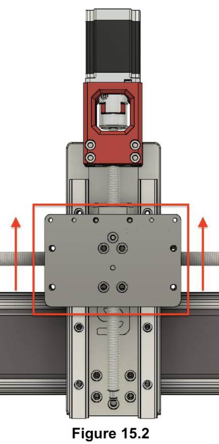
Move the carriages up.
-
Fasten the upper screw of the rail which was loose until now.
-
Tighten the screws of the T-Nutblock.
-
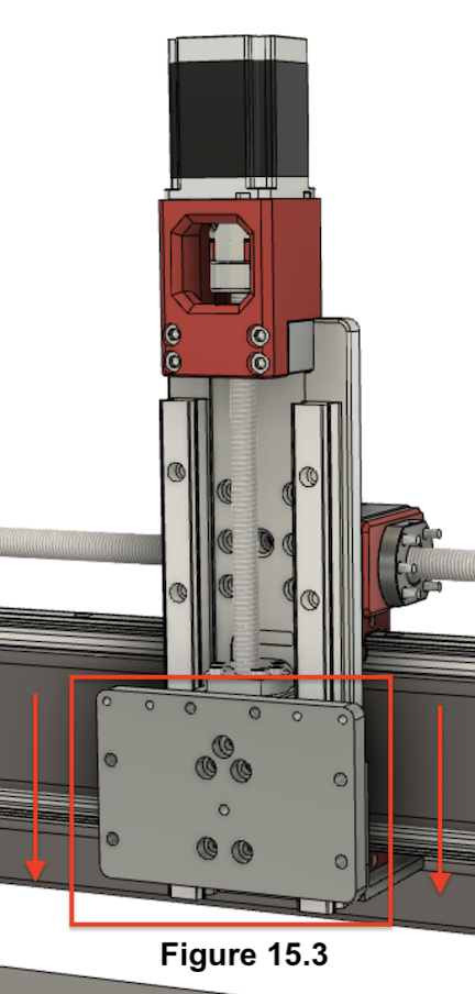
Move carriages down.
-
Tighten the rest of the screws of that rail.
-
Tighten the screws of the BK10/Motor Mount.
-
Gnd gently roll the tram plate along the length of the rail to allow the block wipers to self align. Then tighten the wiper screws up. This will drastically improve their performance.

-
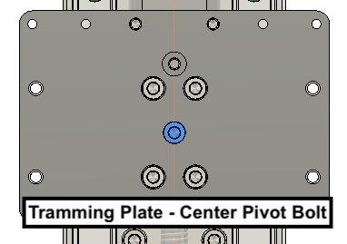
Aluminum tram plate only: Mount center pivot bolt M6x12 socket head on the tramming plate in the hole indicated on the Figure below. It will sit flush on the tam plate and not hold anything together, but it will act as a pivot point for the spindle clamp later:
-
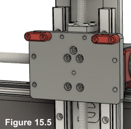
Aluminum tram plate only: Mount 3D printed Spindle tram pieces using (4) M5x20 bolts as shown in Figure 15.5.
-
Prepare the spindle bracket. Drill holes as described here (or use the Fusion file).
-
Mount Spindle bracket: The Spindle bracket is clamped to the tramming plate with (4) M6x40 bolts. The (4) M5x20 bolts are used to push the spindle away from the tram plate for tramming.
-
Aluminum tram plate only: Insert the (2) M6x12 socket head tramming bolts into the 3D printed Spindle tram pieces from above.
-
Before you mount the spindle, make sure that the Z-axis carriages can not slide off the rails. The weight of the spindle can backdrive the ballscrew.
Put a #608 skateboard bearing or a drilled-out M8 (or 5/16") nut on the end of the ballscrew and secure it with the 8mm circlip. Note that this won't prevent the stepper motor from driving the Ballscrew Nut off the ballscrew, but it will prevent gravity from doing so.
-
Loosen the upper and lower spindle bolt and tighten the middle screw. This pushes the bracket open.
-
Insert the Spindle into the bracket from above. It should look like Figure 15.7. Loosen the middle bolt on the spindle bracket and tighten the upper and lower bolts.
If you cannot securely clamp the spindle (without bending your hex wrench lol), try the following: First, run a tap through to the bottom (don't go too far). Second, clear out the chips using compressed air or mechanically. If that still isn't enough, you may need to shorten your bolts with a hacksaw or grinder (2mm should be sufficient). You could also deepen the tapped holes, but you need a 6.8mm drill for that.
WARNING: if you need to loosen the spindle again in the future, make sure the spindle is secure before loosening the middle bolt to prevent the spindle from rapidly dropping.
