¶ Summary
In this step the Z-Axis is mounted to the gantry and aligned vertically
The Z-Axis can either be built with temporary wooden z-plates or with premade aluminium plates. The steps described here are mainly written for the aluminium plates, but differences to the wooden build will be marked. Mainly all tramming parts are not used for the wooden plate. Also, wooden plates use through-holes and bolts with nuts wherever possible and wood-screws where not possible.
This video is a walkthru of the v3 Z: https://www.youtube.com/watch?v=SMazVyW70ic
¶ Prep
¶ Hardware Needed:
- (1) Z-Axis Faceplate (either milled from aluminium or fabricated from plywood. Instructions for both options are on the "Metal" page of this wiki.
- (1) Prepared Aluminum Angle Plate
- (1) Prepared X-Axis Roller Beam from prior step
- (2) HGR20 Linear Rail
- (8) M5x20mm socket head bolts (may come with the rail)
- (10) M6x12mm socket head bolt for pivot, mounting faceplate to X roller, mounting the angle plate, and center bolt on angle plate
¶ Printed Parts Needed
- (4) Rail spacers (if using wood faceplate)
- (1) Tramming bar (only if using aluminium faceplate)
¶ When complete, verify
- There should be (5) bolts from faceplate to X-axis roller.
- There should be (5) bolts from faceplate to Angle Plate.
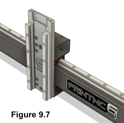
- If using a wood face plate, it should look like:
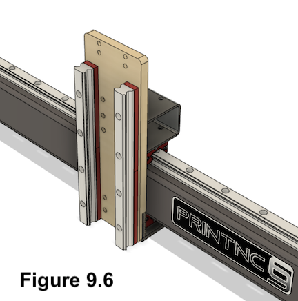
- If using an aluminum milled face plate, it should look like:
¶ Build Steps:
- Attach the HGR20 rails to the faceplate with (8) M5x20mm socket head bolts.
- Wood plate only : Place the 4 printed spacers under the rail first. Use M5 socket head screws going through the wood with nuts on the backside where possible and use wood screws, preferable with a flat underside where there is no space behind the wooden plate
You can leave one rail loose for now, as it needs to be trammed later.
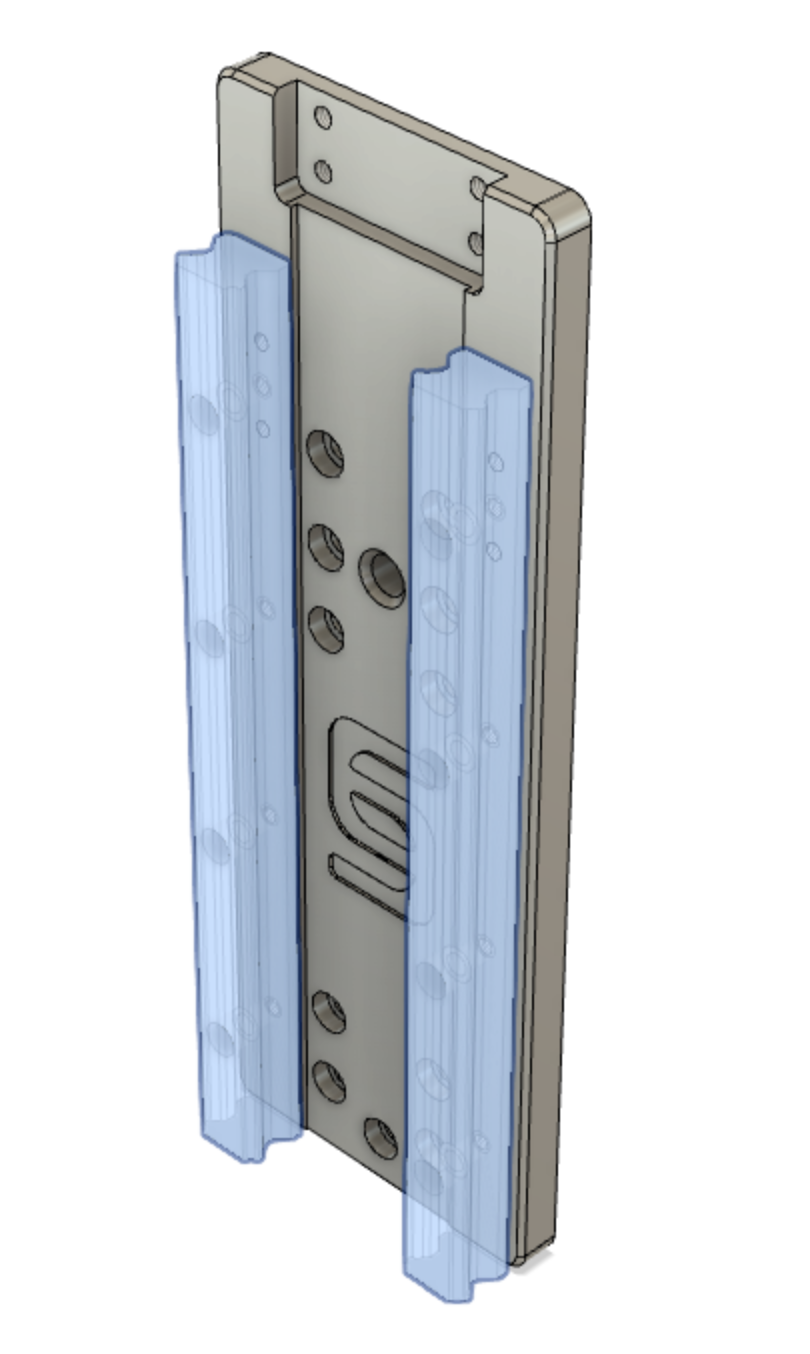
- Loosely mount the faceplate to the aluminum angle using (4) M6x12mm socket head bolts.
- Aluminum plate only: Put (1) M6 screw into the bottom center hole so it can push against the HGR20 carriage for tramming. (The bolt passes through the angle plate in order to contact the carriage. The length of this bolt depends on your build size)
- Wood plate only : Use M6x20 button head bolts in place of the (4) M6x12mm socket head bolts.
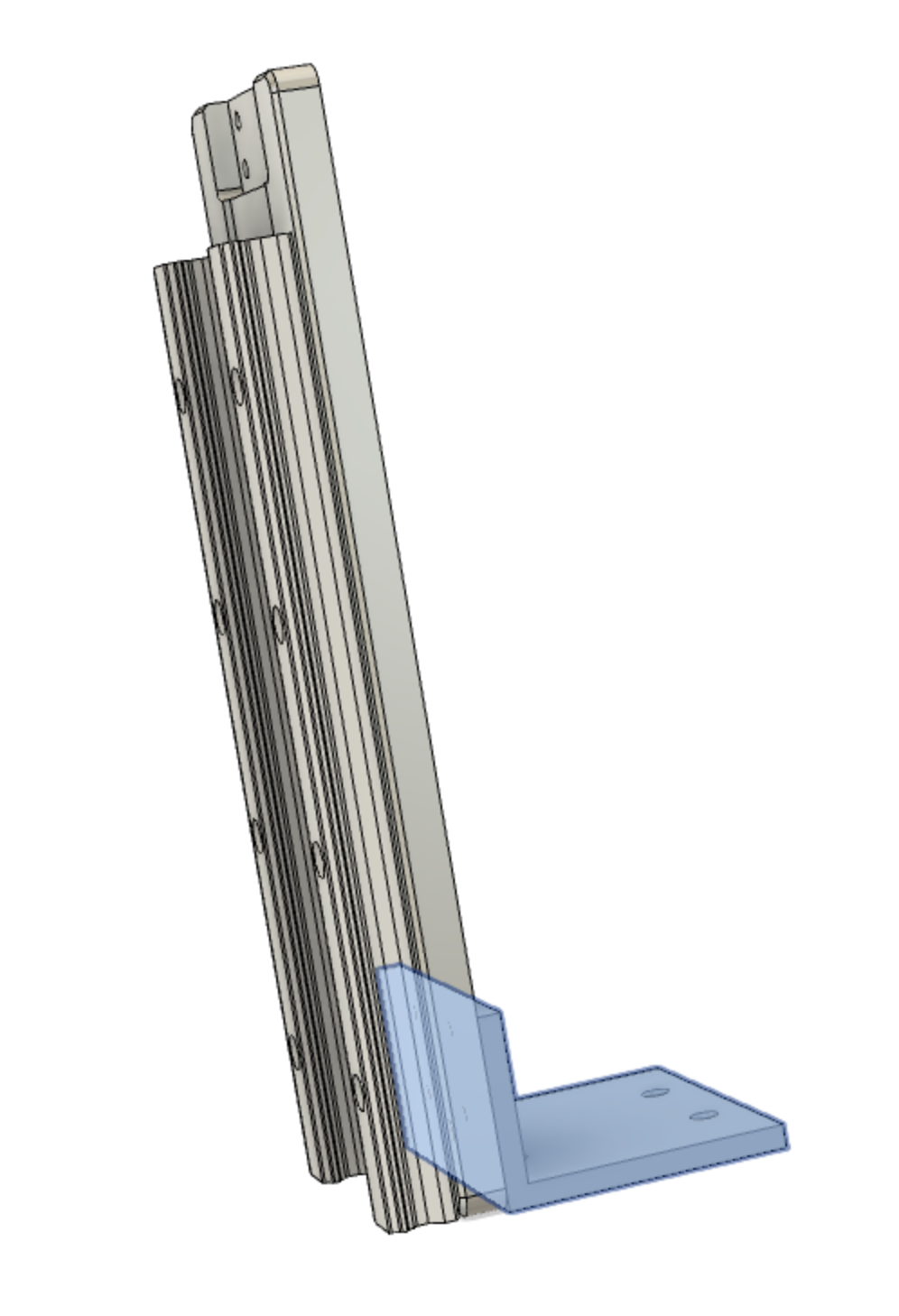
- Aluminum plate only : Screw (1) M6x12mm socket head bolt into the center hole of the front side of the X-axis Roller and place the faceplate on this bolt head so it can swivel around it.
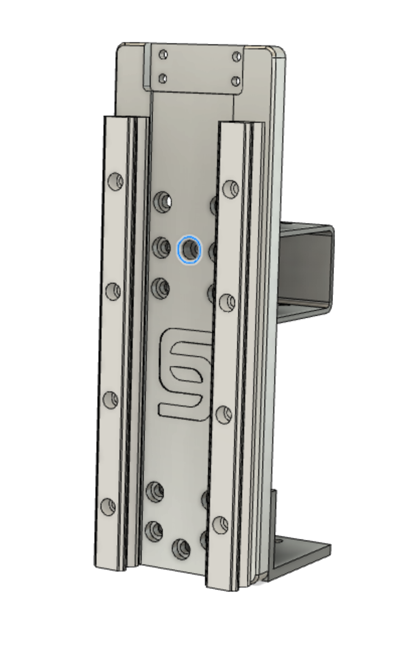
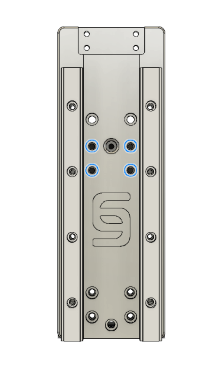
- Loosely Mount the faceplate to the x-roller tube using (4) M6x12mm socket head bolts using 4 of the outer (6) holes. The holes next to the center hole are always used. Depending on your gantry size, either the holes above (for 100mm gantry height) or below (75-80mm gantry height) the center hole are used.
- Wood plate only: use button head screws to spread the load.
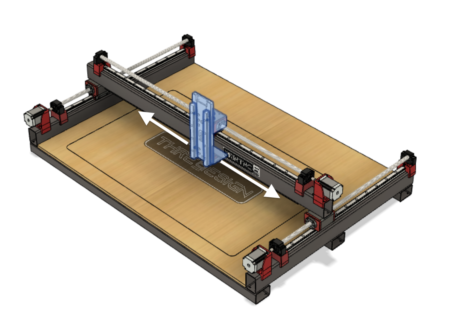
- Slide the Z-Axis assembly back and forth across the X-Axis rails to self align. You may need to readjust the bolts holding the HGW blocks on the Z-Axis.
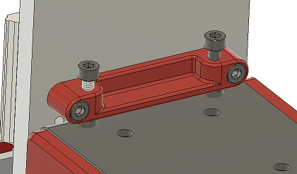
- Aluminum plate only: Mount the tram bar to the back side of the faceplate with M5 socket head screws. Use the holes which position it the closest above the x-roller tube. Put M5 socket head screws into the holes of the tramming bar from the top. See figure below:
- At this point you can do a rough tramming of the faceplate:
- Make sure that the bolts holding the faceplate to the top x-roller front and the aluminium angle to the lower X-roller carriage are loose.
- Make sure that both vertical bolts in the tramming bar and the center tramming bolt in the aluminium angle are not screwed fully in
- Push the aluminium angle back against the HGW20 carriage.
- Now you can use a framing square to check if the faceplate is square to the baseboard in both axis.
- Use the screws in the tramming bar to rotate the faceplate around the Y-axis.
- Use the lower center screw in the aluminium angle part to rotate the faceplate around the X-axis.
-
After everything is squared, tighten all bolts.
-
Move the faceplate on the X-gantry from one side to the other and check if it is square to the baseplate everywhere. If not, slightly move the HGR X-rail to adjust for it. Afterwards tighten the X-rail.
