¶ About
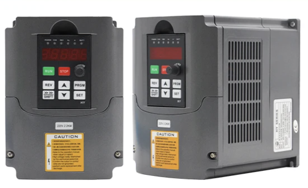
There are many models that look similar to the Huanyang 220v 2.2kw VFD. If yours looks different to the above product photo, do not use this page for configuration.
¶ Product Manual
¶ Wiring & Setup
There are a number of steps that need to be taken in the correct order for everything to work. Please follow each section in order.
¶ 1) Wiring AC In
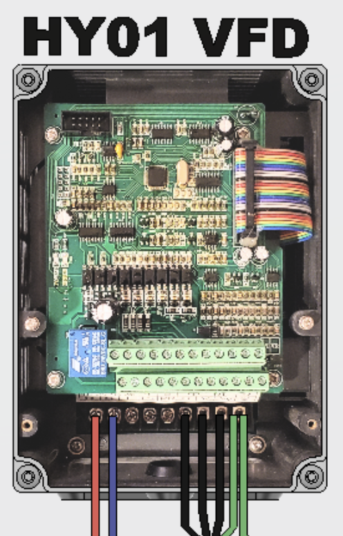
The HY VFD AC wiring is thoroughly documented over in the Wiring & Electronics section of the wiki.
We'll cover things at a super high-level here, please check the VFD AC Wiring section over in the Wiring & Electronics section.
- Wire your
Liveinput to the terminal labelledRon the VFD - Wire your
Neutralinput to the terminal labelledSon the VFD - Wire your
Groundinput to the terminal labelled⏚(Note: The spindle connector must ALSO be connected to this terminal, but not yet)
Don't connect the spindle cable just yet, we need to configure the VFD for first startup before doing so, otherwise we risk damage.
¶ 2) Startup Programming
You MUST configure your VFD properly before attempting to connect & start your spindle up. Not doing so could damage things.
To update a parameter, first click PGRM on the front display. From there, use the UP, DOWN, and SHIFT buttons to select the right register. Then click SET to select. Then use UP, DOWN, and SHIFT again to configure then value, and again, click SET to program it. Some values require a full power off / power on cycle to take affect.
| Parameter | Startup Value | Description |
|---|---|---|
| PD000 | 0 | Parameter Lock. Set to 0 to Unlock updating, set to 1 to Lock. |
| PD001 | 0 | Use the front panel for easier debugging |
| PD002 | 1 | Use the front panel potentiometer. |
| PD005* | 400 | Max Operating Frequency. |
| PD004 | 400 | Base Frequency. |
| PD003 | 400 | Main Frequency. |
| PD006 | 2.5 | Intermediate Frequency. |
| PD007 | 20 | Min Frequency for VF curve. |
| PD008 | 220 | Max output voltage of spindle. (For a 220v spindle) |
| PD009 | 15 | Intermediate voltage for VF curve. |
| PD010 | 8 | Minimum voltage |
| PD011 | 100 | Minimum frequency. Set so the spindle does not overheat at low speeds, as it does not have enough torque to maintain. |
| PD014 | 8 | Acceleration time. Can be lowered for faster acceleration later on. |
| PD015 | 8 | Deceleration time. Can be lowered for faster braking later on. |
| PD070 | 1 | Sets analog voltage range to 0..5v for full RPM range availability on front panel. |
| PD141 | 220 | Motor rated voltage. 220v even for North America. |
| PD142 | 9 | Maximum motor Amp value. 9A for most 220v spindles. |
| PD143 | 2 | Number of spindle poles. 2 for the standard 2.2kw spindle. |
| PD144 | 3000 | RPM of the spindle with a VFD frequency of 50 Hz. Setting this to 3000 gives you a range of 24k RPM for common 2 pole spindles. |
| PD176 | 0 or 1 |
Incoming voltage frequency. Set to If you are in Europe or another country that uses |
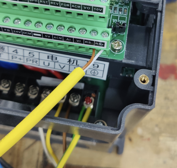
¶ 3) Wiring Spindle Out
Wire your Spindle cable connectors in:
- Wire
Pin 1toU - Wire
Pin 2toV - Wire
Pin 3toW - Wire
Pin 4to⏚(Bottom most very-right)
Once everything is connected, check that you have continuity between your spindle housing and your electronics enclosure AC Ground Input. If you don't, please stop and figure out where the break is and rectify before continuing.
¶ 4) Testing your spindle
NOTE: Please ensure your watercooling loop is all connected and powered on before attempting to start your spindle up, otherwise you will damage it
- Set the potentiometer on the front VFD control panel to somewhere in the middle.
- Power everything up.
- Press the
RUNbutton on the control panel.- Once started, adjust the potentiometer so the screen reads
100Hz
- Once started, adjust the potentiometer so the screen reads
- Take note of which way the spindle is actually spinning, looking from the top.
- If your spindle is spinning clockwise: You're all set.
- If your spindle is spinning counter-clockwise: Power everything down, then swap the
UandVwires in the VFD.
- Wait 5 minutes for everything to warm up.
- Each minute: Adjust the potentiometer so the screen reads
50HzHIGHER, until you hit the maximum of400Hz
¶ 5) Wiring & Configuring RS485
NOTE: Using RS485 is optional, but expands capability of your machine by allowing your CAM program to control the RPM of your spindle dynamically.
Before configuring RS485, ensure that the front panel is working properly, and that you can start, stop, and control the spindle RPM.
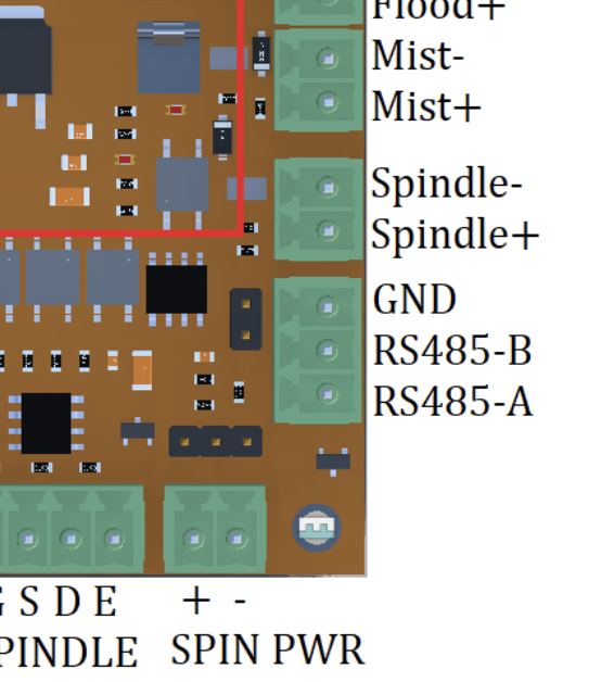
¶ Wiring
A twisted pair of wires should be run between the VFD and your control board.
- Connect a wire between the HY
RS+to the Flexi-HALRS485-Aport. - Connect a wire between the HY
RS-to the Flexi-HALRS485-Bport.
¶ Configuration
Once wired up, update the following parameters to allow you to use RS485 on your VFD.
| Parameter | Value | Description |
|---|---|---|
| PD163 | 1 | Communication address to use. |
| PD164 | 2 |
Communication baud rate.
Set to Set to Set to Set to
|
| PD165 | 3 | Communication data method |
Once you have configured this, follow the Spindle Setup section over in IOSender Configuration [todo]
¶ 6) Wiring & Configuring water pump relay
NOTE: Configuring the water pump relay is entirely optional. It allows you to automatically turn on your watercooling loop whenever your spindle is started.
The HY02D223B (and similar models) VFD has terminal input / outputs to control and monitor various external devices.
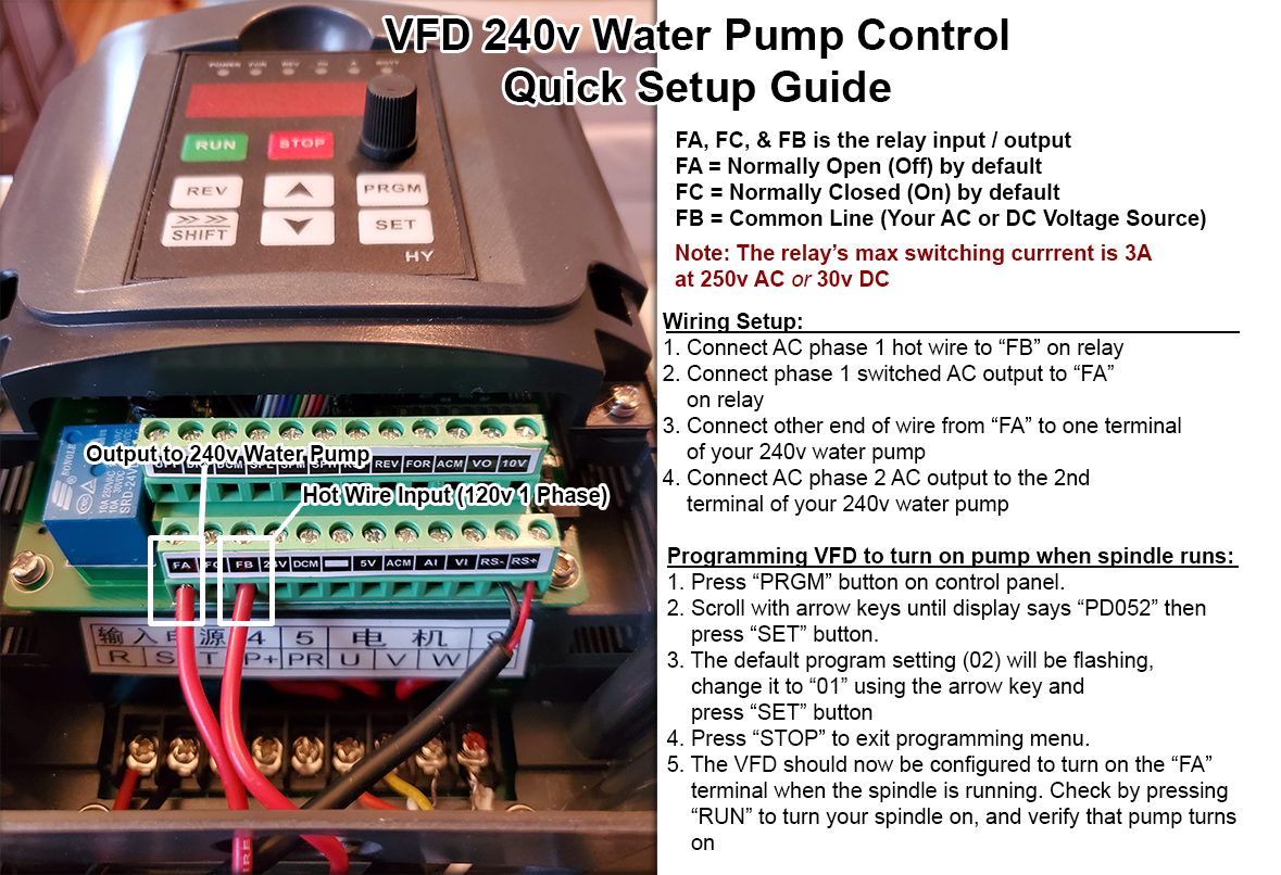
- The “FA” “FC,” and “FB” terminals on the VFD control an internal relay.
- This relay has a maximum switching current of 3 amps at 250v AC or 30v DC, suitable for controlling smaller current devices (such as a water pump).
- FA is Normally Open (off) connection by default.
- FC is Normally Closed (on) connection by default.
- FB is the common terminal - This is where you will connect the power source to be switched with either FA or FC.
Please see below infographic for detail on programming VFD - Text will follow illustration:
¶ Wiring
Connect the power source to be switched into the FB terminal - In this example, we are using 1 phase in a 2 phase 240v AC power source.
- In terminal “FA” connect the wire that will go to your switched current
- Connect the other end of the wire coming from “FA” to your switched device - In this example, we are connecting to 1 terminal of a 240v AC water pump.
- Ensure your switched device has its other necessary connections in place to function when the relay activates - In this example, we make sure that the 2nd phase of our 240v circuit is connected to the 2nd terminal in the 240v water pump.
¶ Configuration
Once wired up, update the following parameters to enable the relay on your VFD.
| Parameter | Value | Description |
|---|---|---|
| PD052 | 01 |
¶ Configuring Analog communication
The HY VFD supports RS485 which should be preferred in all cases. If your controller doesn't support RS485, you can set up an Analog as a fallback.
¶ Wiring
todo
0-10v:
NOTE: Sometimes VFD SETTINGS WONT SAVE IF FOR and DCM and CONNECTED. Remove the connection between these two Terminals to save settings.
1. First Setup PD070 to 1 for 0-10v. 0 setting sets it to 0-5v.
2. PD072: High-end frequency: Set to 400. This sets the frequency represented by the top end of the speed control. (Credit: Corvetteguy50 on Youtube)
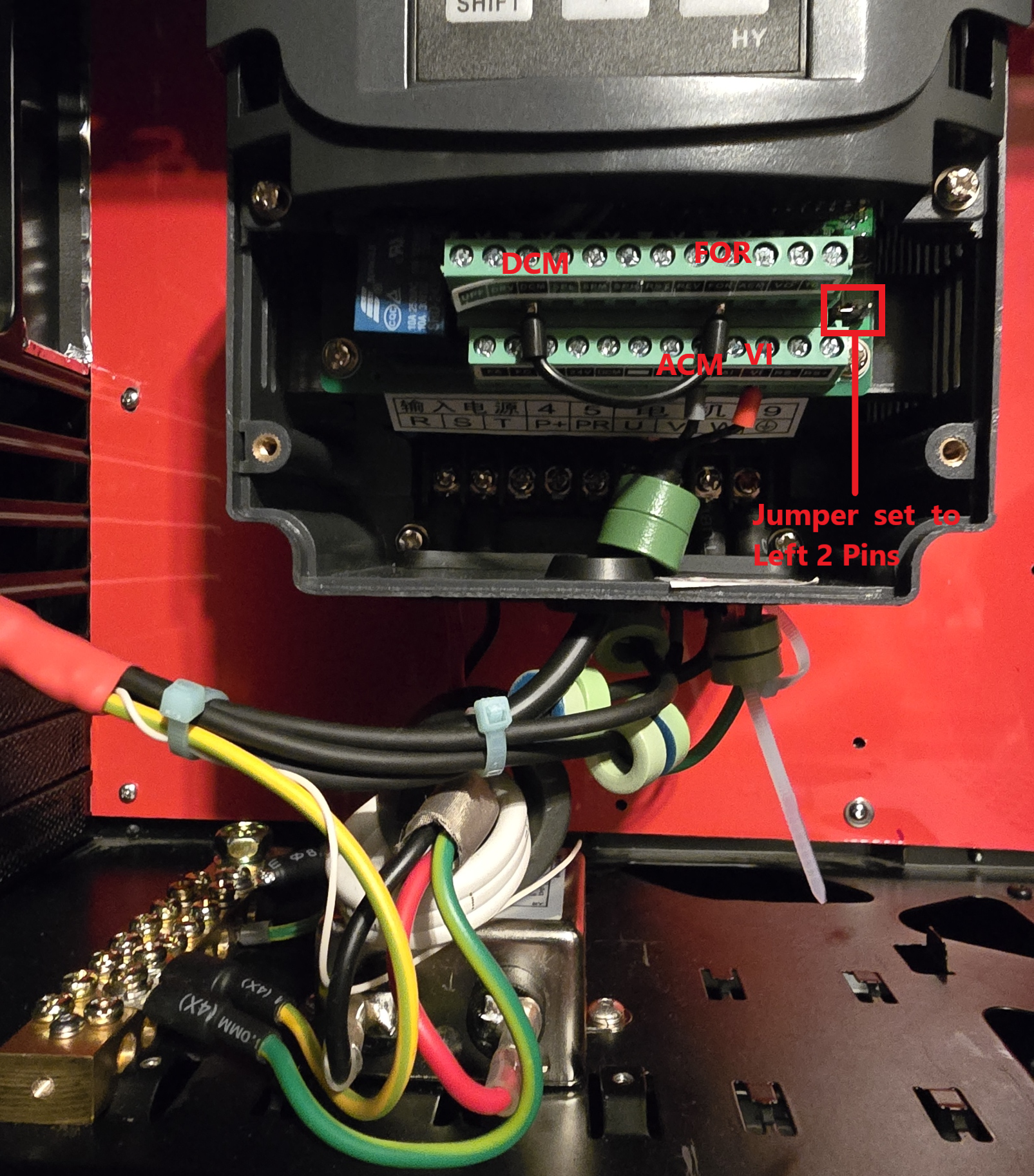
Set the Jumper to short Pins 1 and 2 (VI) to Use external voltage control
Connect VI (Analog voltage in) to +0-10v Line coming from the controller and ACM (Analog common ground) to the -Ve/ground connection coming from the controller.
Connect For (Forward) and DCM (DC common ground) with a Jumper wire Or use a relay to Make the connection between these 2 terminals. This setup will make sure that the motor will only spin forward when the Analog signal comes in.
Set PD001 to 1
Also set PD011 to 0 If you want the spindle to be turned off with the analog signal. Otherwise it will keep spinning at the 100Hz frequency that was initially set when configuring the VFD values.
You can control the Signal gain to Frequency (Hz) with PD072 and PD073 to match the incoming Analog voltage.
Using a PWM to voltage Module to convert a 0-5v PWM signal to 0-10V analog dc output:
Module: https://aliexpress.com/item/1005006986051081.html?
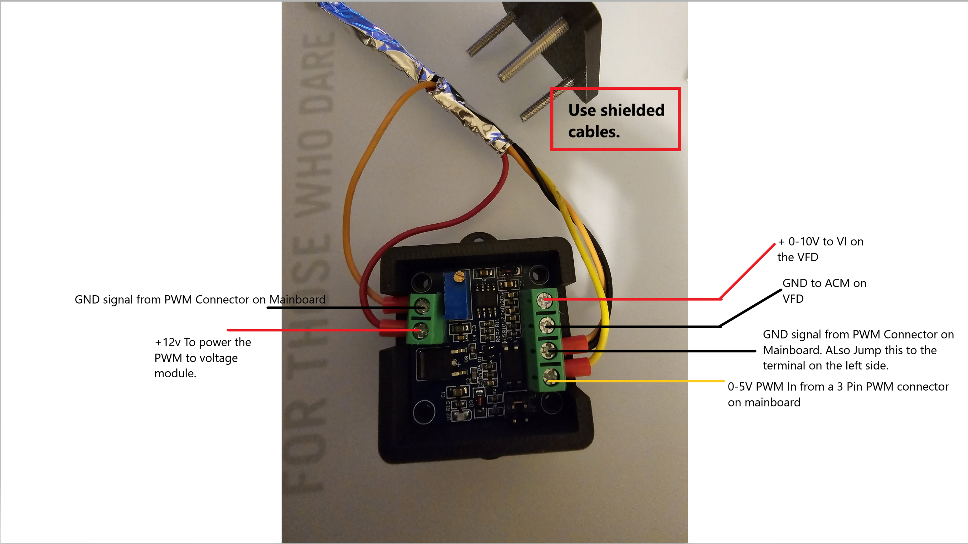
The Module's lowest voltage is around 0.4mV
¶ Configuration
todo