¶ Prep
¶ Tools and Hardware Needed:
- Center punch
- Drill
- 3mm pilot hole drill bit
- 5mm drill bit
- M6 Taper Tap
- Pencil or metal marking scribe
- (2) Y-Axis frame beams
¶ Printed Parts Needed
- Assembly Tool #1 - Y Frame Marker
- Assembly Tool #3 - Y Frame Mid Marker
- Center Line Marker Tool
¶ When complete, verify
- All holes drilled in this step are on the bottom surface of the beams.
- Each beam should have a center line marked on the top surface.
- Each end of the Y-axis frame beams should have 4 holes, as shown in Figure 1.5.
- All Y-axis frame beams should have 4 holes at the center.
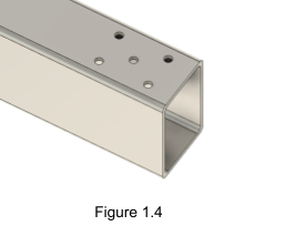
- (optional) Y-axis frame beam can have an extra hole of desired size for cable management, as shown in Figure 1.4.
- All holes except for the optional cable management hole in Figure 1.4 should be threaded to accept an M6 bolt.

¶ Build Steps:
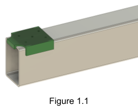
- Position Assembly Tool #1 on the top face of one Y-Axis frame beam with the number on the printed part facing down and all tabs securely holding position as shown in Figure 1.1.

- Mark all 4 corner holes with a center punch.
- (optional) Mark the center hole with a center punch. The center hole is only used once and only on the first beam where a wire will be passed to connect an endstop switch.
- Repeat step 2 on the other end of the Y-Axis frame beam and both ends of the other beam.
- Find and mark the center point of the exposed bottom face of each beam. A pencil will work for this, but a metal marking scribe will result in a "shiny" line that is more easily seen in the center of Assembly Tool #3.
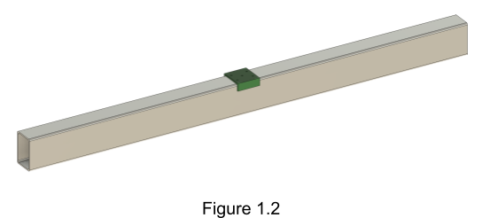
- Position Assembly Tool #3 at the middle of the frame beam as shown in Figure 1.2, using the hole in the center of the printed tool to align it precisely to the center point mark made in the previous step.

- Mark the 4 holes around the edges with a center punch. Do not mark the center hole.
- Drill all marked points with a 3mm pilot drill and then follow up with a 5mm bit.
- Thread all holes made in the previous step except the center hole marked in step 3 with an M6 tap bit. That hole can be tapped, but it’s not necessary.
- Flip the Y-Axis frame beams so the holes are facing down.
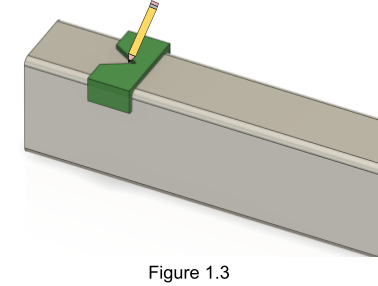
- Position the Center Line Marker Tool on the top face as shown in Figure 1.3.

- Place a pencil or other marking tool at the center of the v shaped grove on the Center Line Marker Tool and hold it there securely.
- Run the Center Line Marker Tool down the length of the beam while using the marking tool to mark the center. Measure your centerline at several places to ensure it is indeed properly centered.
- Repeat previous 3 steps for the other Y-Axis frame beam.