¶ Summary
Prepare all 6 mm threaded and unthreaded holes in the X-Gantry
¶ Prep
¶ Hardware Needed:
- Assembled frame from section 8
- X-Axis gantry beam
- double sided tape
- center punch
- ~6mm diameter marking tool (if used gently an 6 mm drill bit and a hammer can be used or a center punch with a compatible spacer)
- 5 mm drill bit
- M6 tap bit
- 6.5 mm drill bit
- drill
¶ Printed Parts Needed
- Assembly Tool #6 - X Gantry
- Assembly Tool #6a - Gantry Left
- BF12 mount block
- BK12 mount block
- Motor mount
¶ When complete, verify
You have a correct placement for motor mount / BK12 mount / BF12 mount parts.
¶ Build Steps:

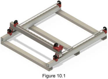
- The X-Axis gantry components need to be testfit in order to find the locations they will be affixed. To begin, place the gantry beam on the Y-Axis roller beams in the frame completed in step 8.
- Start by placing the motor mount at the end of the gantry. Now you need to find the right distance between motor mount and BK12 block. The goal is to have a gap of 6 - 10 mm between motor shaft and ball screw. (the size of the red plastic element in the coupler).
- If you have all standard parts, you can just place the BK12 block ~50 mm away from the motor block.
- Otherwise (if you use different hardware or to be extra sure) mount the BK and BF blocks on the ball screw, mount a motor in the motor mount and testfit the BK-mount so that the gap between motor shaft and ball screw is as wide as the red plastic spacer in the coupler (12 mm).
- Place the HGR20 rail directly next to the BK12-mount
- Place the BF12-Mount directly next to the HGR-Rail
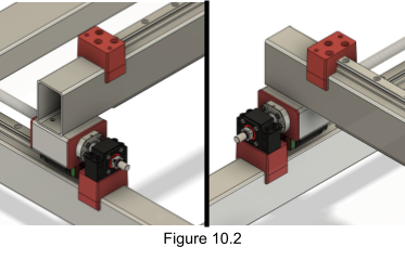
- Ensure the BF12 mount is oriented correctly, as shown in Figure 10.2. The three counterbored holes make a triangle pattern pointing away from the HGR20 rail.

- Mark the three counterbored holes with your marking tool. Ensure the marks are adequately centered. If you’re doing this with a drill bit, be careful to hit the bit very lightly.
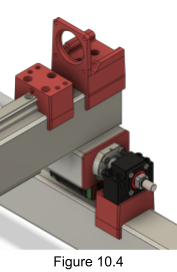
- Ensure the BK12 mount is oriented correctly. The three counterbored holes should form an arrow pointing away from the HGR20 rail as shown in Figure 10.4.

- Mark the three counterbored holes with your marking tool. Ensure the marks are adequately centered. If you’re doing this with a drill bit, be careful to hit the bit very lightly.
- Ensure the motor mount is oriented correctly. It should be oriented as shown in Figure 10.4.

- Once the part is positioned, mark on the beam the location of the two counterbored holes in the printed motor mount with your marking tool. Ensure the marks are adequately centered. If you’re doing this with a drill bit, be careful to hit the bit very lightly.
- Mark the positions of the BK12 mount and BF12 mount on the gantry where they meet the HGR20 rail. Using a square, report the positions to the underside of the steel tube. This will allow you to verify if your bottom rail will not collide with the Y roller in the next build step.
- Dismount all components and remove the rail from the frame assembly.
- Drill all points marked above with an 5mm bit.
- Thread all holes made in the previous step with an M6 tap bit.
- Place Assembly Tool #6 on one end of the X-Gantry on the underside.
- Mark the holes and drill them with a 6.5mm drill bit.
- Place the X-Gantry on the Y-Rollers. Align the drilled holes from (16.) with one Y-Roller and fix it in place with some bolts.
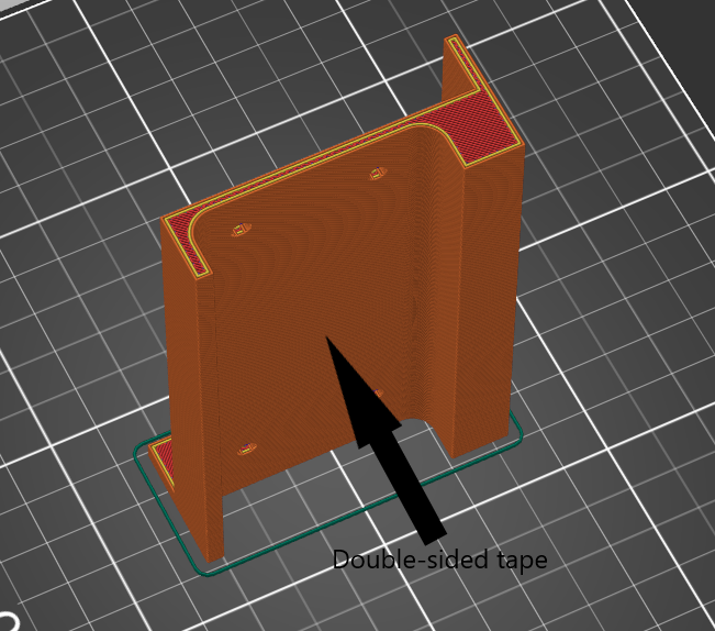
- Place a piece of double sided tape on the upper side of assembly tool 6a and remove the protective part.

- Gently lift the X-Gantry on the loose end and insert the assembly tool 6a so it aligns with the Y-Roller
- Lower the beam so it rests on assembly tool 6a which should stick to the gantry
- Remove the screws added in step 17, then flip the gantry. You'll then have access to the assembly tool 6a, sticked to the underside of the X-gantry.
- Mark the holes in assembly tool 6a with a center punch and drill them with a 6.5mm drill bit.