¶ Stepper Motor Drivers
If using closed loop stepper drivers, these are typically supplied with the correct driver as a package. Therefore, this information is only applicable to the open loop stepper motors.
The stepper motor driver takes the movement command sent from the controller and applies the power to the stepper motor. In simple terms its switching on a higher voltage supply using a low voltage supply.
The drivers are available in many different types and only a handful will be discussed here.
The type of controller chosen to drive the project will have an effect on the type of driver chosen.
¶ Onboard Stepper Drivers
If a controller is chosen that has permanent onboard drivers (such as the duet 2 wifi/ethernet), this will limit the maximum voltage that can be used to drive the stepper motors. Higher voltage equals more speed and a higher current will equal more torque. The current that can be supplied to the drivers will also be limited.
¶ Stepstick Type Stepper Drivers
These are the type of drivers used in the 3D printing world. As most 3D printers use Nema 17 sized motors, the voltage and current that they can supply is more than adequate but in a similar fashion to the onboard stepper drivers, these will ultimately limit the type of motors that can be driven.
¶ External Stepper Drivers
This type of driver are the most suitable for the printNC. Some examples are listed below:
- TB6600 - This is the driver that is supplied in the AliExpress basic kit and is a good entry-level driver. It can be used with up to 40v DC power supplies and can output up to 3.5A rms (4A peak). manual
- DM542 - This is considered to be the next step up from the TB6600 It is included in the Aliexpress pro kit. It can be used with up to 45v DC power supplies and can output up to 3.0A rms (4.2A peak). manual
- DM556 - It can be used with up to 45v DC power supplies and can output up to 4.0A rms (5.6A peak). manual
- DM860H - It can be used with up to 62V DC power supplies and can output up to 5.1A rms (7.2A peak).
- Note that a database of step times for various drivers is found here.
¶ Matching Drivers to Motors
¶ summary
"As a cautionary note, some [] Drive manufacturers advertise their product’s output phase current levels as a peak value, using larger values is typically a marketing tactic. For continuous duty motor operation in a room temperature environment, you set the output RMS (Root Mean Square) current of the Chopper Drive to the rated RMS coil current of the motor” link
¶ Are stepper motors rated for peak or rms current?
Labels on motors and motor data sheets typically list an amps/ phase rating. amps/phase specifies how much average current each winding or phase can handle without burning out the motor. It should be obvious that this value is the same as the amps RMS rating. Source
Stepper Motors and Stepper-Based Linear Actuators are typically rated as RMS (Root Mean Square) values. Source
All stepper motors are rated in RMS Current, and when Full Stepping, 200 steps/rev, there is no difference in stepper drivers that output RMS Current and those that output Peak Current. Source
¶ But Why are ratings RMS?
Manufacturers generally list RMS because RMS current is constant regardless of microstepping amounts. Source In addition, damage to stepper motors occurs due to overheating. Heat is generated by RMS current, not peak current.
Example
In this excerpt from the cnczone.com forums, a Leadshine application engineer helps a user select the correct driver/motor configuration.
[poster] “I have two different 8-wire steppers in parallel configuration with two different Leadshine digital drives at 1/8 microsteps. I'm looking for to match my driver current settings with motor specs.”
| Motor1, PK299-E4.5A (RATED CURRENT A/PHASE) Bipolar (Parallel) 6.2A Bipolar (Series) 3.18A Unipolar 4.5A |
DM860 DIGITAL DRIVER REF Current - Peak Current ...... 4.28A ---- 5.14A 4.86A ----- 5.83A 5.43A ----- 6.52A 6.00A ----- 7.20A |
| Motor2, M60STH88 (RATED CURRENT A / PHASE) Bipolar (Parallel) 4.2A Bipolar (Series) 2.1A Unipolar 3A |
DM556 DIGITAL DRIVER Peak Current - RMS Current ..... 3.8A ----- 2.7A 4.3A ----- 3.1A 4.9A ----- 3.5A 5.6A ----- 4.0A |
[engineer] "The peak current =1.3*RMS ,normally ,we set RMS for the motor. For your motor 1 ,PK299-E4.5A ,and if the connection type is parallel ,the current setting on DM860 should be 6.00A ----- 7.20A. For motor 2 .the DM556 current setting is 5.6A ----- 4.0A (for parallel connection).
¶ connecting 4-wire steppers to DM542
4 lead motors are the least flexible but easiest to wire. Speed and torque will depend on winding inductance. In setting the driver output current, multiply the specified phase current by 1.4 to determine the peak output current
¶ Selecting for 8-wire Steppers to DM556
Parallel connected 8-lead stepper motors are typically implemented in applications which higher torque at high speed movement is required. Compared with series connection, a parallel connected stepper motor has lower inductance and therefore have better torque performance at higher speed movement. Although setting the drive output current to 1.4 times of driven motor phase current will get the most torque, it is suggested to set an EM556S’s output current (peak of sinusoidal) to no more than 1.2 times the stepper motor’s phase current to prevent overheating. Refer to the figure 12 for how to connect an 8-lead stepper motor for parallel connection. Source
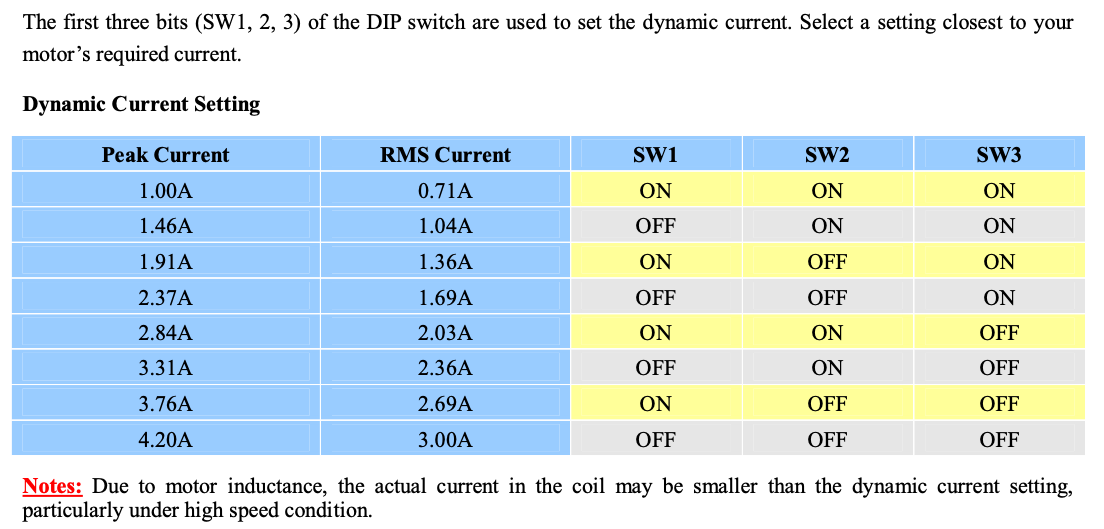
¶ Setting the Dip Switches on Your Drivers
Your dip switch settings will depend on your drivers, motors, and desired micro stepping ratio.
This tutorial is designed for the default DM542 and 3A motor setup. NOTE: Some switches may be reversed for some drivers, please check the manual and/or the table on your drivers for appropriate settings.
¶ Switches 1-3
As seen above, RMS driver current is set to the phase current of the stepper motor (3A). Therefore, All three switches should be set to ‘OFF’. However, to start (and especially if using if using plastic motor mounts), reduce your current by 1-2 steps.
¶ Switch 4
Switch 4 gives you the option to reduce the current (and therefore heat) of motors when at a standstill. To Activate this feature, set the position to 'OFF"
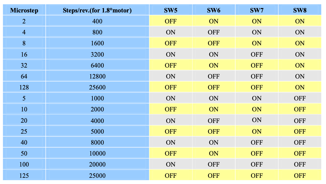
¶ Switches 5-8
These switches set the micro step settings. More micro stepping is generally better but it is very easy to overload your controller with commands, limiting your top speed. Safe advise would be to set your micro stepping at 4, 5, or 8.
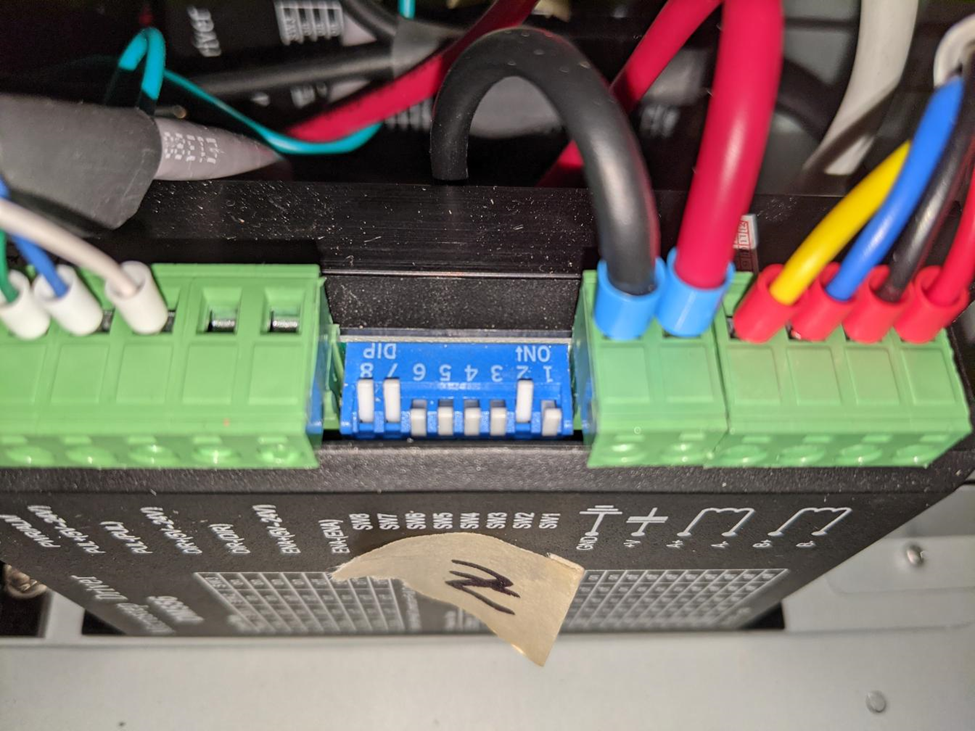
This is what a DM542 Driver looks like matching with a 3A motor, running at 8 micro steps, and with standstill current reduction activated.
¶ Frequently Asked Questions - PrintNC Stepper Drivers
¶ Q - I'm about to place my order, any final thoughts on drivers?
Trader: It's worth asking this in Discord to see if any issues or positive discoveries have come up lately with given models and suppliers, but one other tip is that new builders consider ordering one extra driver when building a PrintNC. The incremental cost is tiny and it has a lot of benefits… It's a spare, it allows you to read the driver text (e.g. dip switch tables) once they are mounted in the enclosure (space constraints almost always mean they are vertical mount and closely spaced, making reading them impossible), it gives you something to test new temporary settings with, something to use on a test bench etc. etc.
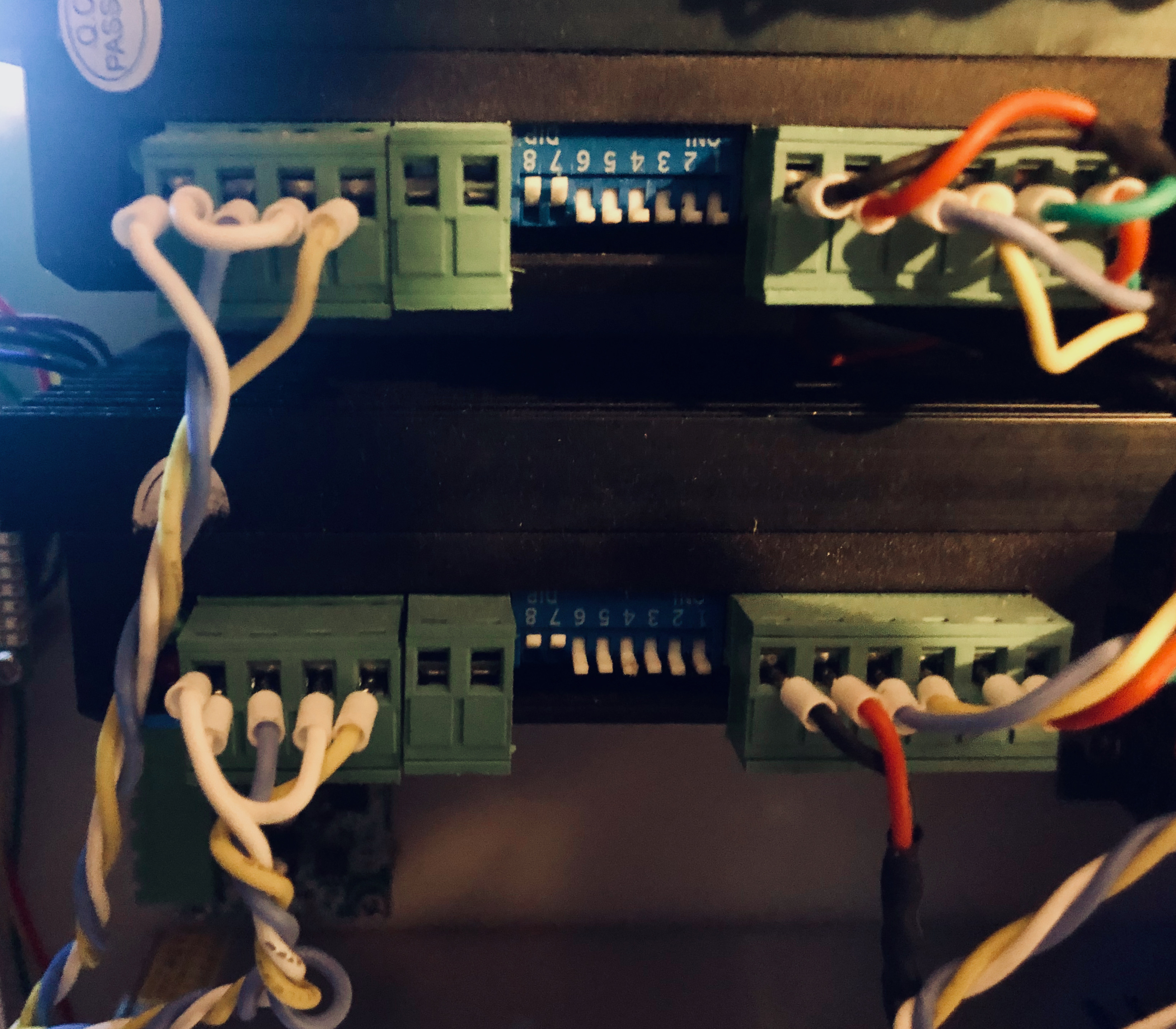
¶ Q - How do I tell which way is “ON” for my dip switches?
Logan: Make sure to note which way is "on" for your driver. I've seen the dip switches reversed on in some drivers
gerrg: That's a good call
Logan: For your image OFF is toward the front and ON is toward the back.
gerrg: correct. people kept asking me which direction was on, and i didn't have any idea what they were talking about. the switch is clearly only "NO" or "not NO". duh
¶ Q - What is the difference between a DM542 and DM556?
@logan: 542 is 50V, 4.2A max, 556 is 50V, 5.6A max though input voltage is 45V max.
¶ Q – How do I know what step rate I need?
ballen: Step rate = (movement rate/pitch) X (microstep X 200).
So 100mm/s on 10mm pitch at 8 microsteps requires 16khz step rate to perform. Note that the movement rate in the calculation is in mm/second not mm/minute as more commonly used when discussing feed rates. 100mm/s = 6000mm/min.
The 1610 or 2010 ballscrews in the current PrintNC design are 10mm pitch, making calculations easy.
Jitter determines max step rate in that with too much jitter the signal for one pulse could over lap into the next pulse. Jitter is the consistency of a signal.
¶ Q - So the PC latency affects what microstepping you can run on your stepper drivers?
ballen: Effectively, yes. It determines how fast your PC can reliably send a signal without bit errors occurring.
Being FPGA based boards, Mesa ethernet boards can handle higher stepping which is one reason they are popular.
Logan: Well, I'm running 5 microsteps because that's 0.01mm per step and I'm not going to get more accuracy than that so why bother with more.
¶ Q – Any updates on the the blinky green light on the DM556 stepper driver investigation?
Noot: I wonder if the enable pins may also be in play. My blinky green drivers rotate as well - I'll power cycle the box and the squealer will often change. Does anyone have the enable pins connected?
Noot: Just read a forum post on poweron sequence... I have a separate power switch for my stepper PSU... I will try powering the drivers after the bob/linuxcnc is up to see if it makes a difference
Noot:
"Short-voltage and Over-voltage protection
When power supply voltage is lower than 13VAC or +18VDC, short-voltage protection will be
activated and power indicator LED will blink."
That's from a totally different leadshine drive manual unfortunately
gerrg: if i power on my drivers seperately, after the mesa, i have the same issue. Also, i tried connecting the enable + and - to 5V and gnd from the mesa card, and it didn't change anything for me
UPDATE MAY 21, 2021: Trader: Another data point - I have store supplied DM556s that arrived around late January and I just wired them up to my Cisco PSU and they work just fine.
¶ Q - Are settings (and specifications) standardized for DM542 and DM556 drivers? Is it reasonable to look at the datasheets or manuals I can find online and assume they apply to my (AliExpress or other) sourced DM542s and DM556s?
Josh 🇺🇸 — This is going to make you say "duh", but here goes: I've played with drivers from 4 different manufacturers in the last month. once the drivers are installed in my enclosure I can no longer see the paint markings on the top of the driver (switch instructions). I had gotten into a habit of just pulling up a DM542 or DM556 manual on my phone for setting the dip switches. all DM556's do not have the same dip switch settings. the DM556 I am currently using have opposite "current" settings than the manual I had been using from Google. spent a lot of time trying to get my roller faceplate alignment literally perfect because I couldn't understand why it was stalling... even in easy spots. my current was on the lowest setting (versus the highest)
¶ Q - How to mount DM542 and DM556 drivers
Q: I made these printed brackets to mount the drivers to Din rail, do you like them?
A: No. The manual instructs to mount the drivers directly to a metal plate (e.g. the enclosure) to help dissipate the heat from the driver